Custom is the new Desktop
Being efficient without a mouse
Every once in a while I am on the customizing trip and want to mix up my computing experience. Perhaps it sounds weird after just repairing the Surface Laptop to now blog about customizing Linux to the max, but I am constantly switching operating systems and interfaces. The best devices I own are the Mac Mini M1 and my trusty Lenovo Yoga Slim 7. One running MacOS (or Asahi), the other one pure Linux. If the Yoga just had a high DPI screen...
This time around I am trying how to be efficient on a Laptop without using the touchpad much. I think I would not run the setup I'll describe on a big monitor, it feels just way more comfy running on a small Laptop screen.
Sneak Peak
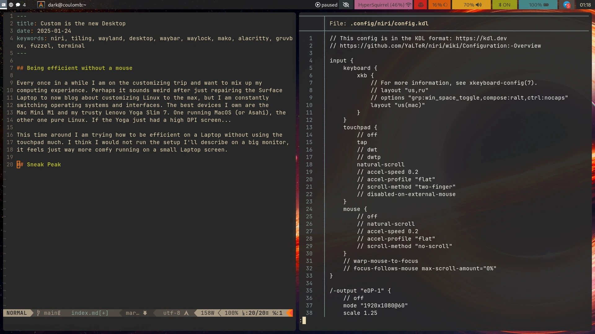
This is what it will look like, and I am using the following software:
- SDDM as login manager
- Niri as the wayland compositor
- Waybar as the title bar and control center
- Fuzzel as an application launcher
- Alacritty as a customizable terminal
- Mako for notifications
- Wayidle to run the screen locker automatically
- Swaylock "effects-improved" fork as a screen locker
- Pwvucontrol to set up my audio
- Overskride to set up bluetooth
- SwayBG for the background image
- XWayland Satellite to be able to use older software
- and parts of KDE for the XDG portals and KWallet for password management
Oh and as a colorscheme I'll use Gruvbox. As I am on Arch btw. I'll use the packages Archlinux provides or link to the AUR where necessary.
Login manager (SDDM)
If you don't want to run a text-mode login or auto-login on boot you need some frontend for logging in. I'll opt for SDDM here because my alternate Desktop has always been KDE Plasma and so this one is already installed.
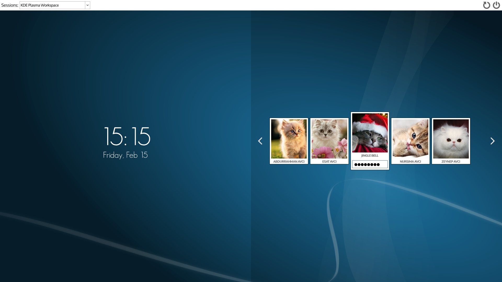 (Screenshot stolen from the SDDM Github)
I am running it in X11 mode, configuration as it comes with Arch. Nothing fancy to see here.
Niri the Wayland compositor
The star of the show. I wanted to try a tiling environment but with a low configuration overhead (ha see where that got me!). So I don't want to describe where each and every window goes. I don't want to waste space either and I want it to be a fit for a Laptop screen.
Then I heard of niri. The idea of niri is that (by default) all windows are maximized vertically and can take up variable width slices of the screen horizontally. It's a bit like the App switchers on iPhone and modern Android.
You can use the keyboard to shrink windows vertically if you need to, but by default you will get an infinite strip of horizontally layed out windows.
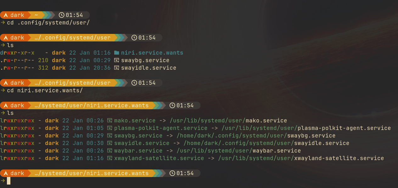
As we're running a bunch of independent software here with no desktop environment glueing the parts together we'll use a systemd (go away haters!) user session to keep everything running:
-
Create the systemd user directory if not existing:
mkdir ~/.config/systemd/user -
We're running the niri session as a systemd service, so we're putting
everything we want to run into the
niri.service.wantsdirectory so it does not interfere with other desktops we may have installed in parallel. -
To be able to use niri on a basic level we're just linking
waybarin for now:ln -s /usr/lib/systemd/user/waybar.service waybar.service -
Install niri, on Arch it's just
sudo pacman -S niri waybarto get those two packets. -
To be able to run something on your session make sure to have at least one
of
AlacrittyorFuzzelinstalled.
The default configuration of niri has
Mod+T
bound to run Alacritty and
Mod+D
to run Fuzzel.
Go on, log into the niri session now an get yourself a Terminal by pressing
Super+T
(if you're new to this,
Super
is usually the
Windows
key).
First segment of
.config/niri/config.kdl
:
input {
    keyboard {
        xkb {
            layout "us(mac)"
        }
    }
    touchpad {
        tap
        natural-scroll
    }
    mouse {
    }
}
The snippet on top defines my keyboard layout to the US Macintosh variant. I
prefer the Mac variants because they have useful combining characters on
the
Right Alt
layer like
Right Alt+u
for Umlauts and other useful stuff.
See the niri documentation on what else is possible.
Segment of
.config/niri/config.kdl
:
layout {
    gaps 8
    center-focused-column "never"

    preset-column-widths {
        proportion 0.33333
        proportion 0.5
        proportion 0.66667
    }

    default-column-width { proportion 0.5; }

    focus-ring {
        off
    }

    border {
        off
    }

    struts {
    }
}
This part basically defines how the window layout works, I completely
deactivated any focus ring or borders as I am using the
waybar
for that and
like a clean look.
Segment of
.config/niri/config.kdl
:
prefer-no-csd
screenshot-path "~/Pictures/Screenshots/Screenshot from %Y-%m-%d %H-%M-%S.png"
As said, I like it clean and as we're managing our windows with the keyboard I
want the applications to rely on server side decorations (there are none though).
Segment of
.config/niri/config.kdl
:
binds {
    Mod+T { spawn "alacritty"; }
    Mod+Space { spawn "fuzzel"; }
    Mod+B { spawn "firefox"; }

    XF86AudioRaiseVolume allow-when-locked=true { spawn "wpctl" "set-volume" "@DEFAULT_AUDIO_SINK@" "0.1+"; }
    XF86AudioLowerVolume allow-when-locked=true { spawn "wpctl" "set-volume" "@DEFAULT_AUDIO_SINK@" "0.1-"; }
    XF86AudioMute        allow-when-locked=true { spawn "wpctl" "set-mute" "@DEFAULT_AUDIO_SINK@" "toggle"; }
    XF86AudioMicMute     allow-when-locked=true { spawn "wpctl" "set-mute" "@DEFAULT_AUDIO_SOURCE@" "toggle"; }

    XF86MonBrightnessUp allow-when-locked=true { spawn "brightnessctl" "s" "+5"; }
    XF86MonBrightnessDown allow-when-locked=true { spawn "brightnessctl" "s" "5-"; }
}
I am only showing some of the keybinds here because the rest of them are basically on default settings or are custom to you, but the important ones:
- The first section are shortcuts that run applications, I am using Alacritty , Fuzzel and Firefox
-
For the multimedia keys I use the command line tool for Wireplumber
wpctl -
For screen brightness I use
brightnessctl
You will not have any fancy popups for displaying volume or brightness but
I'll handle that in the waybar configuration.
Segment of
.config/niri/config.kdl
:
environment {
    DISPLAY ":1"
}
I am setting the
DISPLAY
env variable here to
:1
to be able to run
XWayland applications.
:0
is already in use by
SDDM
so we have to use
display one here. This may be fragile if you log in multiple times, but I am
not planning to.
Segment of
.config/niri/config.kdl
:
workspace "terminal"
workspace "browser"
workspace "chat"

window-rule {
    geometry-corner-radius 6
    clip-to-geometry true
}

window-rule {
    match app-id="Alacritty"
    open-on-workspace "terminal"
}

window-rule {
    match app-id=r#"firefox$"#
    open-on-workspace "browser"
    open-maximized true
}

window-rule {
    match app-id=r#"firefox$"# title="^Picture-in-Picture$"
    open-floating true
    open-maximized false
}

window-rule {
    match app-id="org.telegram.desktop"
    open-on-workspace "chat"
}

window-rule {
    match app-id="org.kde.tokodon"
    open-on-workspace "chat"
}
Lastly I define three named workspaces and put some windows on them by default. Additionally I am maximizing Firefox and making sure the picture in picture window will be floating and not integrated into the tiles.
That's it, this is my niri config. Niri will reload its configuration after you change something, so you can try it live.
If you need to find an App ID for window rule matching run this command and switch to the window in question quickly (you have 3 seconds ;) ):
sleep 3 ; niri msg focused-window
Waybar... It has to be configured
The next big chunk of configuration is for waybar . The cool thing: it's very flexible. The bad thing: it's very flexible.
The default config sucks by the way, so go on overwrite it with something that makes more sense:
Module config
Be aware: It is possible that your browser does not display all symbols in
the following config. They are from the Nerdfont installed on my computer,
but I am not including that currently in my CSS here.
First part of:
~/.config/waybar/config.jsonc
{
    "position": "top",
    "height": 24,
    "spacing": 4,
    "modules-left": [
        "niri/workspaces",
        "niri/window"
    ],
    "modules-center": [
    ],
    "modules-right": [
        "mpris",
        "idle_inhibitor",
        "network",
        "power-profiles-daemon",
        "backlight",
        "wireplumber",
        "bluetooth",
        "battery",
        "tray",
        "clock"
    ]
}
Base config:
- Show the bar on top
- Define size
- Define loaded modules
To get a list of modules run
man waybar
and scroll down. To get
documentation for a module config run
man waybar-<module>
.
I am using:
- The workspace switcher
- Current window title
- Media playback icon
- Screensaver deactivator
- Network info
- Power profile
- Backlight
- Audio volume
- Bluetooth status
- Battery status
- System tray
- Clock

Configuration segment for workspace switcher
"niri/workspaces": {
    "format": "{icon}",
    "format-icons": {
        "chat": "\udb82\udf79",
        "browser": "\udb81\udd9f",
        "terminal": "\ue795"
    }
},
Set up workspace switcher. To save space use Icons for the named workspaces.

Configuration segment for window title
"niri/window": {
    "format": "{title}",
    "icon": true,
    "icon-size": 20,
    "rewrite": {
    }
},
Current window title, show the app icon and title. If you want you can set up rewrite rules to rename windows that have awkward titles.

Configuration segment for multimedia playback
"mpris": {
    "format": "\uf144 {status}",
    "tooltip-format": "{player}"
}
Multimedia playback icon, show player in tooltip.

Configuration segment for idle inhibitor
"idle_inhibitor": {
"format": "{icon}",
"format-icons": {
"activated": "",
"deactivated": ""
}
},
Idle inhibitor: Just disables the automatic screen locking on click

Configuration segment for network
"network": {
"format-wifi": "{essid} ({signalStrength}%) ",
"format-ethernet": "{ipaddr}/{cidr} ",
"tooltip-format": "{ifname} via {gwaddr} ",
"format-linked": "{ifname} (No IP) ",
"format-disconnected": "Disconnected ⚠",
"format-alt": "{ifname}: {ipaddr}/{cidr}"
},
Network info, show SSID when on wifi and IP address on wired. The alt format shows up on click.

Configuration segment for power profile
"power-profiles-daemon": {
"format": "{icon}",
"tooltip-format": "Power profile: {profile}\nDriver: {driver}",
"tooltip": true,
"format-icons": {
"default": "",
"performance": "",
"balanced": "",
"power-saver": ""
}
},
Power profile switcher: Just set some icons

Configuration segment for backlight
"backlight": {
"format": "{percent}% {icon}",
"format-icons": ["", "", "", "", "", "", "", "", ""],
"on-scroll-down": "brightnessctl s +5",
"on-scroll-up": "brightnessctl s 5-"
},
Backlight control: reacts to scrolling to increase and decrease screen brightness.

Configuration segment for audio
"wireplumber": {
"format": "{volume}% {icon}",
"format-muted": "Muted ",
"format-icons": {
"headphone": "",
"hands-free": "",
"headset": "",
"phone": "",
"portable": "",
"car": "",
"default": ["", "", ""]
},
"min-length": 10,
"on-click": "pwvucontrol",
"on-click-right": "wpctl set-mute @DEFAULT_AUDIO_SINK@ toggle",
"on-scroll-up": "wpctl set-volume @DEFAULT_AUDIO_SINK@ 5%-",
"on-scroll-down": "wpctl set-volume @DEFAULT_AUDIO_SINK@ 5%+"
},
Audio volume, set some icons and run
pwvucontrol
when clicking,
right click mutes/unmutes and scrollwheel changes volume

Configuration segment for bluetooth
"bluetooth": {
    "format-on": "\udb80\udcaf ON",
    "format-off": "\udb80\udcb2 OFF",
    "format-connected": "\udb80\udcb1 {device_alias}",
    "on-click": "overskride",
    "on-click-right": "bluetoothctl power $(bluetoothctl show | grep -q \"Powered: yes\" && echo off || echo on)",
    "min-length": 8
    },
Bluetooth module:
- Just a bluetooth icon and the most recently connected device.
-
On click run
Overskrideto configure bluetooth - On right click toggle Bluetooth power

Configuration segment for battery
"battery": {
"states": {
"warning": 30,
"critical": 15
},
"format": "{capacity}% {icon}",
"format-full": "{capacity}% {icon}",
"format-charging": "{capacity}% ",
"format-plugged": "{capacity}% ",
"format-alt": "{time} {icon}",
"format-icons": ["", "", "", "", ""],
"min-length": 10
},
Battery status, set some thresholds and icons.

Configuration segment for systray
"tray": {
    "icon-size": 20,
    "spacing": 10
},
System tray: just set geometry

Configuration segment for clock
"clock": {
    "tooltip-format": "<big>{:%Y %B}</big>\n<tt><small>{calendar}</small></tt>",
    "format-alt": "{:%Y-%m-%d}"
},
Set format for the clock
Theme
The theme is based on gruvbox colors and is stored
in:
~/.config/waybar/style.css
Theme CSS file
* {
    /* `otf-font-awesome` is required to be installed for icons */
    font-family: FontAwesome, Cantarell, sans-serif;
    font-size: 13px;
}

window#waybar {
    background-color: rgba(40, 40, 40, 0.75);
    color: #ffffff;
    transition-property: background-color;
    transition-duration: .5s;
}

window#waybar.hidden {
    opacity: 0.2;
}

button {
    /* Use box-shadow instead of border so the text isn't offset */
    box-shadow: inset 0 -3px transparent;
    /* Avoid rounded borders under each button name */
    border: none;
    border-radius: 0;
}

/* https://github.com/Alexays/Waybar/wiki/FAQ#the-workspace-buttons-have-a-strange-hover-effect */
button:hover {
    background: inherit;
    box-shadow: inset 0 -3px #ffffff;
}

/* you can set a style on hover for any module like this */
#wireplumber:hover {
    background-color: #a37800;
}

#workspaces button {
    padding: 0 5px;
    background-color: transparent;
    color: #ffffff;
}

#workspaces button:hover {
    background: rgba(0, 0, 0, 0.2);
}

#workspaces button.focused {
    background-color: #64727D;
    box-shadow: inset 0 -3px #ffffff;
}

#workspaces button.urgent {
    background-color: #eb4d4b;
}

#mode {
    background-color: #64727D;
    box-shadow: inset 0 -3px #ffffff;
}

#clock,
#battery,
#cpu,
#memory,
#disk,
#temperature,
#backlight,
#network,
#pulseaudio,
#wireplumber,
#custom-media,
#tray,
#mode,
#idle_inhibitor,
#scratchpad,
#power-profiles-daemon,
#mpd {
    padding: 0 10px;
    color: #ffffff;
}

#window,
#workspaces {
    margin: 0 10px;
}

/* If workspaces is the leftmost module, omit left margin */
.modules-left > widget:first-child > #workspaces {
    margin-left: 0;
}

/* If workspaces is the rightmost module, omit right margin */
.modules-right > widget:last-child > #workspaces {
    margin-right: 0;
}

#clock {
    background-color: #282828;
    color: #fbf1c7;
}

#tray {
    background-color: #504945;
    color: #fbf1c7;
}

#battery {
    background-color: #458588;
    color: #3c3836;
}

#battery.charging, #battery.plugged, #battery.not-charging {
    color: #fbf1c7;
    background-color: #458588;
}

@keyframes blink {
    to {
        background-color: #cc241d;
        color: #fbf1c7;
    }
}

/* Using steps() instead of linear as a timing function to limit cpu usage */
#battery.critical:not(.charging) {
    background-color: #458588;
    color: #fbf1c7;
    animation-name: blink;
    animation-duration: 0.5s;
    animation-timing-function: steps(5);
    animation-iteration-count: infinite;
    animation-direction: alternate;
}

#bluetooth {
    color: #3c3836;
    background-color: #98971a;
}

label:focus {
    background-color: #000000;
}

#wireplumber {
    background-color: #d79921;
    color: #3c3836;
}

#wireplumber.muted {
    background-color: #d65d0e;
}

#backlight {
    background-color: #d65d0e;
    color: #3c3836;
}

#power-profiles-daemon {
    padding-right: 15px;
    background-color: #cc241d;
    color: #3c3836;
}

#network {
    background-color: #b16286;
    color: #3c3836;
}

#tray > .passive {
    -gtk-icon-effect: dim;
}

#tray > .needs-attention {
    -gtk-icon-effect: highlight;
    background-color: #eb4d4b;
}

#idle_inhibitor {
    background-color: #2d3436;
}

#idle_inhibitor.activated {
    background-color: #ecf0f1;
    color: #2d3436;
}
Fuzzel: a launcher that just works
Fuzzel is a very simple program, when it opens it gives you a list
of all
*.desktop
files it finds and you can fuzzy search for an application
and run it.
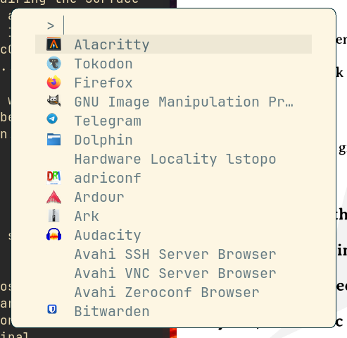
You can configure the font it's using, the position, shortcuts to run something directly from the list without using the search etc.
It has another function though; you can feed a list of options to it and it
just echoes the selected entry back to
stdout
for usage in scripts.
The following snippet for example shows a menu with one entry in it: "Firefox"
echo -en "Firefox\0icon\x1ffirefox" | fuzzel --dmenu
I just set the font to
JetBrains Mono
in
~/.config/fuzzel/fuzzel.ini
:
font="JetBrains Mono"
Alacritty: fast terminal

Alacritty is a fast OpenGL accelerated terminal. I configured the theme to
gruvbox:
Alacritty config in
~/.config/alacritty
[general]
live_config_reload = true
import = [ "~/.config/alacritty/gruvbox.toml" ]

[window]
opacity = 0.95

[scrolling]
history = 10000

[font]
normal = { family = "JetbrainsMonoNL Nerd Font", style = "Regular" }
size = 10.5
builtin_box_drawing = false

[bell]
animation = "Ease"
duration = 100
color = "#3c3836"

[selection]
save_to_clipboard = true

[cursor]
style = { shape = "Block", blinking = "On" }
blink_interval = 333

[mouse]
hide_when_typing = true
The settings you can set here are pretty basic:
- Window transparency
- Scrollback buffer (10000 for me)
- Font
- Visual bell instead of beeping
- Save selections to clipboard
- Make the cursor blink and
- the mouse disappear when typing
I am importing the theme from an additional theme file:
Theme file
[colors.primary]
background = "#282828"
# soft contrast:
#  background = "#32302f"
foreground = "#ebdbb2"

[colors.normal]
black = "#282828"
red = "#cc241d"
green = "#98971a"
yellow = "#d79921"
blue = "#458588"
magenta = "#b16286"
cyan = "#689d6a"
white = "#a89984"

[colors.bright]
black = "#928374"
red = "#fb4934"
green = "#b8bb26"
yellow = "#fabd2f"
blue = "#83a598"
magenta = "#d3869b"
cyan = "#8ec07c"
white = "#ebdbb2"
But just the terminal color settings is not enough to feel good. I could go to more lengths for my vim configuration but that will be probably another blog entry as I have to explain how to use those modules in detail. So watch this place.
One simple thing I can tell you: for a fancy prompt install
starship
and
run the following commands to activate it:
starship preset gruvbox-rainbow >~/.config/starship.toml
starship init bash >> ~/.bashrc
Restart your terminal and be happy about the colorful prompt :)
Mako to be informed

Mako will be used to have a notification bubble show up when some application
wants to have your attention. It can do many things but the configuration is
simple:
Mako config in
~/.config/mako/config
font=Cantarell 10.5
background-color=#282828ff
text-color=#ebdbb2ff
border-size=1
border-color=#83a598ff
border-radius=6
default-timeout=30000
I just set some colors, made the border radius match the one of niri and configured a font that is actually installed.
But how does the system know that we want to use Mako? On a desktop environment the desktop manager would carry out that burden, on our Lego version of assembling a desktop you got to keep the parts.
Let's have systemd handle that for us:
ln -s \
  /usr/lib/systemd/user/mako.service \
  ~/.config/systemd/user/niri.service.wants/mako.service
Swayidle/Swaylock, automatic screen locking is an app?
As already said, you get to keep the parts, not even screen locking or turning off the screen are handled automatically.
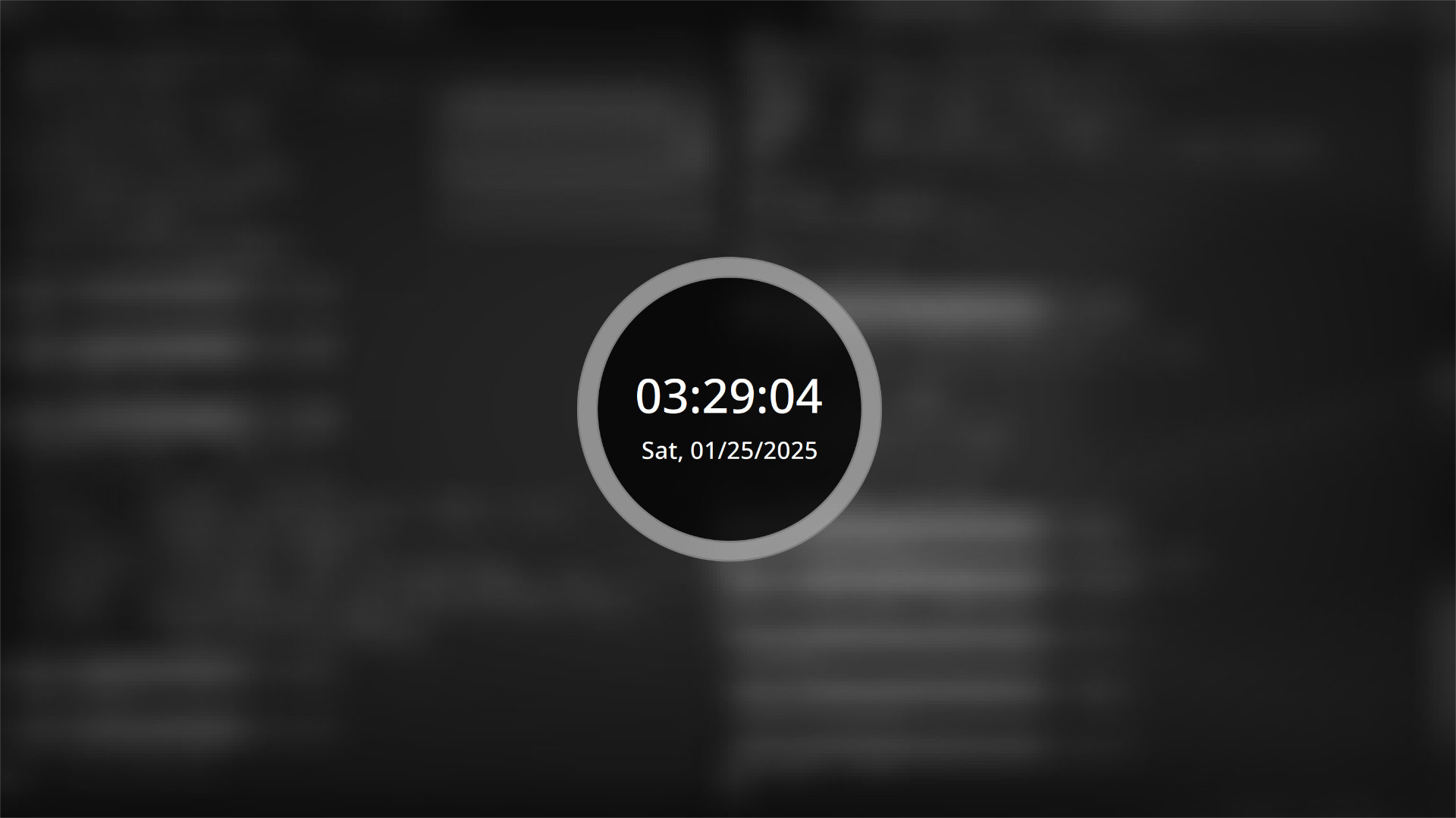
As we want to configure how it looks (the default is terrible) we create
another config file.
Config file in
~/.config/swaylock/config
screenshots
clock
indicator-idle-visible
grace=5
indicator-radius=150
indicator-thickness=20
effect-scale=0.2
effect-blur=5x2
effect-greyscale
effect-scale=5
effect-vignette=0.5:0.5
line-color=808080ff
ring-color=a0a0a0dd
key-hl-color=ffffffff
text-color=ffffffff
ring-ver-color=ffffffff
inside-ver-color=ffffffff
Be aware I am using a fork of a fork of a fork here:
swaylock-effects-improved
, if you don't want to
pull it from the AUR
I am afraid you have to compile it yourself.
So that's the lock screen, but nobody calls for it to show up yet, hey you
guessed it... let's use systemd:
Service definition in
~/.config/systemd/user/swayidle.service
[Unit]
PartOf=graphical-session.target
After=graphical-session.target
Requisite=graphical-session.target

[Service]
ExecStart=/usr/bin/swayidle -w timeout 601 'niri msg action power-off-monitors' timeout 600 '/usr/bin/swaylock' before-sleep '/usr/bin/swaylock'
Restart=on-failure
After creating the file reload systemd:
systemctl --user daemon-reload
and link the thing to niri:
ln -s \
  ~/.config/systemd/user/swayidle.service \
  ~/.config/systemd/user/niri.service.wants/swayidle.service
If you want to lock your screen with a keyboard shortcut you can add it to the niri config like this:
binds {
    Mod+L { spawn "/usr/bin/swaylock"; }
}
PWVucontrol, pretzel fingers while typing
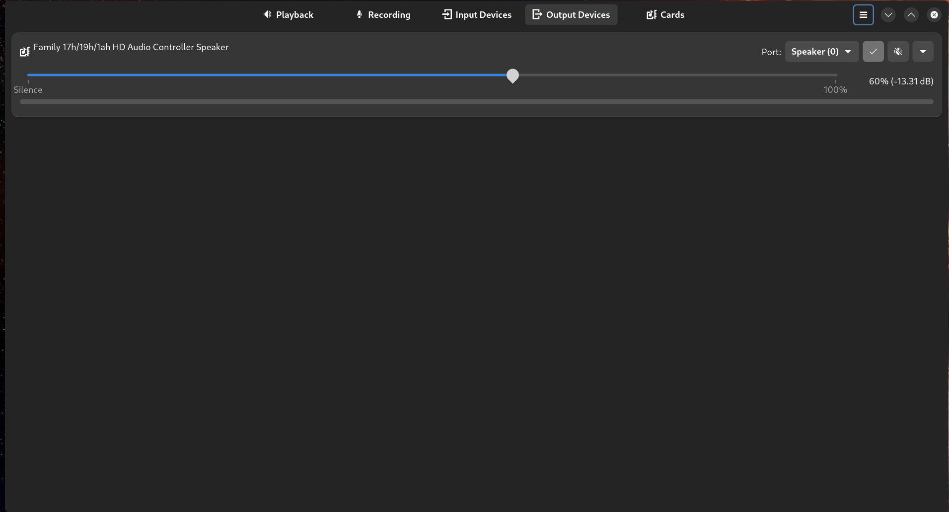
You could use
pavucontrol
(another pretzel) to control your audio but
as modern systems use wireplumber in the background and we love to use another
rust application I went for the native pretzel.
Get it from the AUR if you're on Arch or take the meson build in your own hands.
Nothing to configure here, just for completeness sake (you need to control your audio somehow...)
Overskride, how did that name happen?
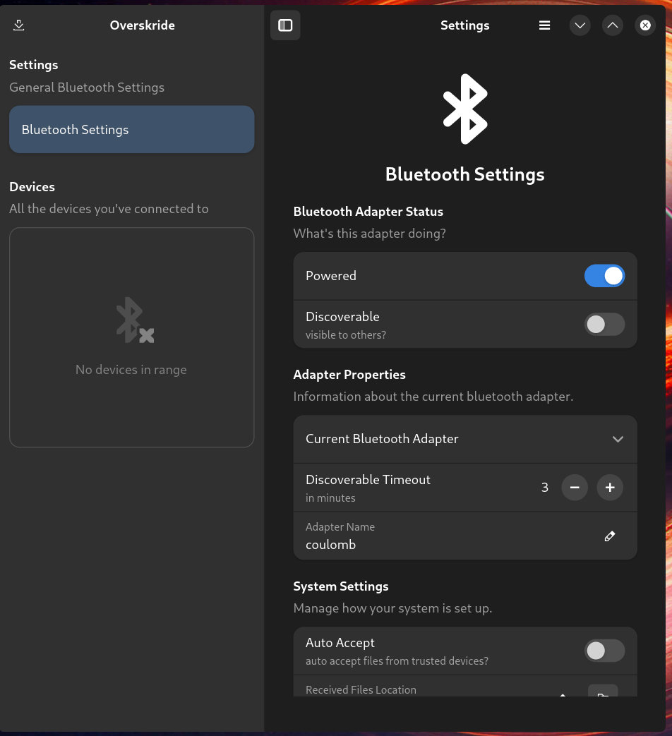
Please tell me, how do you find this application after you installed it and did not call it by name for half an hour? No, I am waiting...
Another
libadwaita
application, another application written in rust... hey
I am not trying to force using rust applications, it just so happens they are
good mostly!
Nothing to configure here either, but a nice interface to your bluetooth settings.
Again:
- AUR
- Or build it with meson yourself: https://github.com/kaii-lb/overskride
SwayBg, this reminds me of barebones X11 in 1999
And now for something that absolutely reminds me of the late 90ies and early 2000s... At that time I worked not just with Linux but all kinds of Unix boxes. We had Solaris, HPUX, AIX and my personal Workstation in my job back then a SGI Octane with IRIX. Why am I remembered of that? Well the default background of X11 after startup was a checkered black and white pattern that really killed you if you had to look at it on a lower resolution monitor. In addition to that not all window managers were desktop environments and it seems nobody found it necessary to set a background image on XFree86.
If you used CDE or some kind of desktop environment you basically got a solid color or some kind of marble texture as a background. But if you experimented with X11 stuff sometimes you defaulted to a simple window manager which did not replace the patterned background. There were tools to set a background image... Wayland with a simple compositor is the same.
I mean at least the background is solid black...
To fix that you have to run a wayland client that basically presents the background. And you guessed it: something or someone has to start that.
Drumroll... let's use systemd!
Systemd service file for swaybg in
~/.config/systemd/user/swaybg.service
[Unit]
PartOf=graphical-session.target
After=graphical-session.target
Requisite=graphical-session.target

[Service]
ExecStart=/usr/bin/swaybg -m fill -i "%h/Pictures/Wallpaper/blackhole.jpg"
Restart=on-failure
The
%h
in the
ExecStart
line will be replaced with your home directory.
Finally link the thing to niri:
ln -s \
  ~/.config/systemd/user/swaybg.service \
  ~/.config/systemd/user/niri.service.wants/swaybg.service
Xwayland sattelite to run that software from 1999 (or GIMP)
As we were at retro things: Lets enable Xwayland for older applications. Niri
does not by default have support for Xwayland, but there's a fix for that:
Xwayland-satellite
. That thing just listens to the X11 display socket and
spawns in windows that render the older X11 apps.
You need to run it, but basically you don't have to configure it.
ln -s \
  /usr/lib/systemd/user/xwayland-satellite.service \
  ~/.config/systemd/user/niri.service.wants/xwayland-satellite.service
And as you probably have noticed in the niri config: we already set the
DISPLAY
environment variable to
:1
so the applications will find the
emulated X11 server.
Hey it seems you're at the end! Restart your session and test if it works!
