<?xml version="1.0" encoding="utf-8"?>
<feed xmlns="http://www.w3.org/2005/Atom">

 <title>Dunkelstern</title>
 <subtitle>Dunkelstern Blog</subtitle>
 <logo>https://dunkelstern.de/images/dunkelstern.png</logo>
 <link href="https://dunkelstern.de" />
 <link href="https://dunkelstern.de/atom.xml" rel="self" type="application/atom+xml" />
 <id>urn:uuid:76240202-407c-5636-a2ba-25ec3f2d0efa</id>
 <updated>2025-01-25T04:26:46+01:00</updated>


 <entry>
  <title>Custom is the new Desktop</title>

  <link rel="alternate" type="text/html" href="https://dunkelstern.de/articles/2025-01-24/index.html"/>
  <id>urn:uuid:8ae80cc7-a680-536e-8c1c-06d2bcdaa756</id>
  <published>2025-01-24T00:00:00+01:00</published>
  <updated>2025-01-25T04:26:42+01:00</updated>
  <summary><![CDATA[ <p>
 Every once in a while I am on the customizing trip and want to mix up my
computing experience. Perhaps it sounds weird after just repairing the Surface
Laptop to now blog about customizing Linux to the max, but I am constantly
switching operating systems and interfaces. The best devices I own are the
Mac Mini M1 and my trusty Lenovo Yoga Slim 7. One running MacOS (or Asahi), the
other one pure Linux. If the Yoga just had a high DPI screen...
</p>
 ]]></summary>
  <content type="html"><![CDATA[ <h2 id="being-efficient-without-a-mouse">
 Being efficient without a mouse
</h2>
<p>
 Every once in a while I am on the customizing trip and want to mix up my
computing experience. Perhaps it sounds weird after just repairing the Surface
Laptop to now blog about customizing Linux to the max, but I am constantly
switching operating systems and interfaces. The best devices I own are the
Mac Mini M1 and my trusty Lenovo Yoga Slim 7. One running MacOS (or Asahi), the
other one pure Linux. If the Yoga just had a high DPI screen...
</p>
<p>
 This time around I am trying how to be efficient on a Laptop without using the
touchpad much. I think I would not run the setup I'll describe on a big monitor,
it feels just way more comfy running on a small Laptop screen.
</p>
<h2 id="sneak-peak">
 Sneak Peak
</h2>
<p>
<img alt="Screenshot" class="center" src="https://dunkelstern.de/articles/2025-01-24/sneak_peak.webp"/>
</p>
<p>
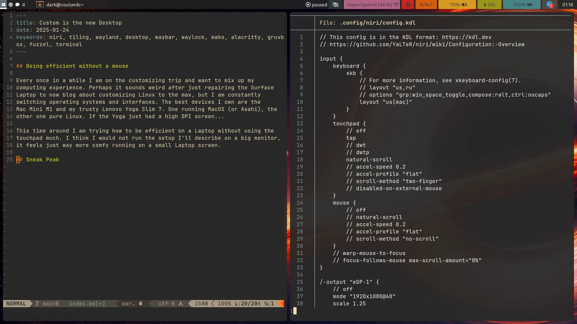
 This is what it will look like, and I am using the following software:
</p>
<ul>
<li>
<a href="https://github.com/sddm/sddm/">
   SDDM
  </a>
  as login manager
 </li>
<li>
<a href="https://github.com/YaLTeR/niri">
   Niri
  </a>
  as the wayland compositor
 </li>
<li>
<a href="https://github.com/Alexays/Waybar">
   Waybar
  </a>
  as the title bar and control center
 </li>
<li>
<a href="https://codeberg.org/dnkl/fuzzel">
   Fuzzel
  </a>
  as an application launcher
 </li>
<li>
<a href="https://alacritty.org/">
   Alacritty
  </a>
  as a customizable terminal
 </li>
<li>
<a href="https://github.com/emersion/mako">
   Mako
  </a>
  for notifications
 </li>
<li>
<a href="https://sr.ht/~whynothugo/wayidle/">
   Wayidle
  </a>
  to run the screen locker
automatically
 </li>
<li>
<a href="https://github.com/samchouse/swaylock-effects-improved">
   Swaylock "effects-improved" fork
  </a>
  as a screen locker
 </li>
<li>
<a href="https://github.com/saivert/pwvucontrol">
   Pwvucontrol
  </a>
  to set up my audio
 </li>
<li>
<a href="https://github.com/kaii-lb/overskride">
   Overskride
  </a>
  to set up bluetooth
 </li>
<li>
<a href="https://github.com/swaywm/swaybg">
   SwayBG
  </a>
  for the background image
 </li>
<li>
<a href="https://github.com/Supreeeme/xwayland-satellite">
   XWayland Satellite
  </a>
  to be
able to use older software
 </li>
<li>
  and parts of KDE for the XDG portals and KWallet for password management
 </li>
</ul>
<p>
 Oh and as a colorscheme I'll use Gruvbox.
As I am on Arch btw. I'll use the packages Archlinux provides or link to the
AUR where necessary.
</p>
<h3 id="login-manager-sddm">
 Login manager (SDDM)
</h3>
<p>
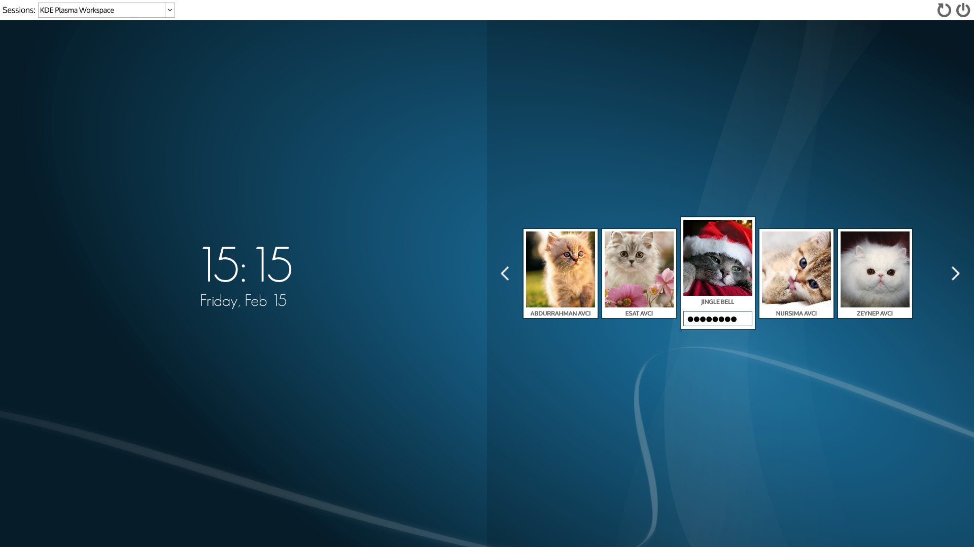
 If you don't want to run a text-mode login or auto-login on boot you need some
frontend for logging in. I'll opt for SDDM here because my alternate Desktop
has always been KDE Plasma and so this one is already installed.
</p>
<p>
<img alt="SDDM Screenshot" class="center" src="https://dunkelstern.de/articles/2025-01-24/sddm.jpg"/>
 (Screenshot stolen from the SDDM Github)
</p>
<p>
 I am running it in X11 mode, configuration as it comes with Arch. Nothing
fancy to see here.
</p>
<h3 id="niri-the-wayland-compositor">
 Niri the Wayland compositor
</h3>
<p>
 The star of the show. I wanted to try a tiling environment but with a low
configuration overhead (ha see where that got me!). So I don't want to describe
where each and every window goes. I don't want to waste space either and I want
it to be a fit for a Laptop screen.
</p>
<p>
 Then I heard of niri. The idea of niri is that (by default) all windows are
maximized vertically and can take up variable width slices of the screen
horizontally. It's a bit like the App switchers on iPhone and modern Android.
</p>
<p>
<img alt="Systemd config screenshot" class="right" src="https://dunkelstern.de/articles/2025-01-24/systemd.png"/>
</p>
<p>
 You can use the keyboard to shrink windows vertically if you need to, but by
default you will get an infinite strip of horizontally layed out windows.
</p>
<p>
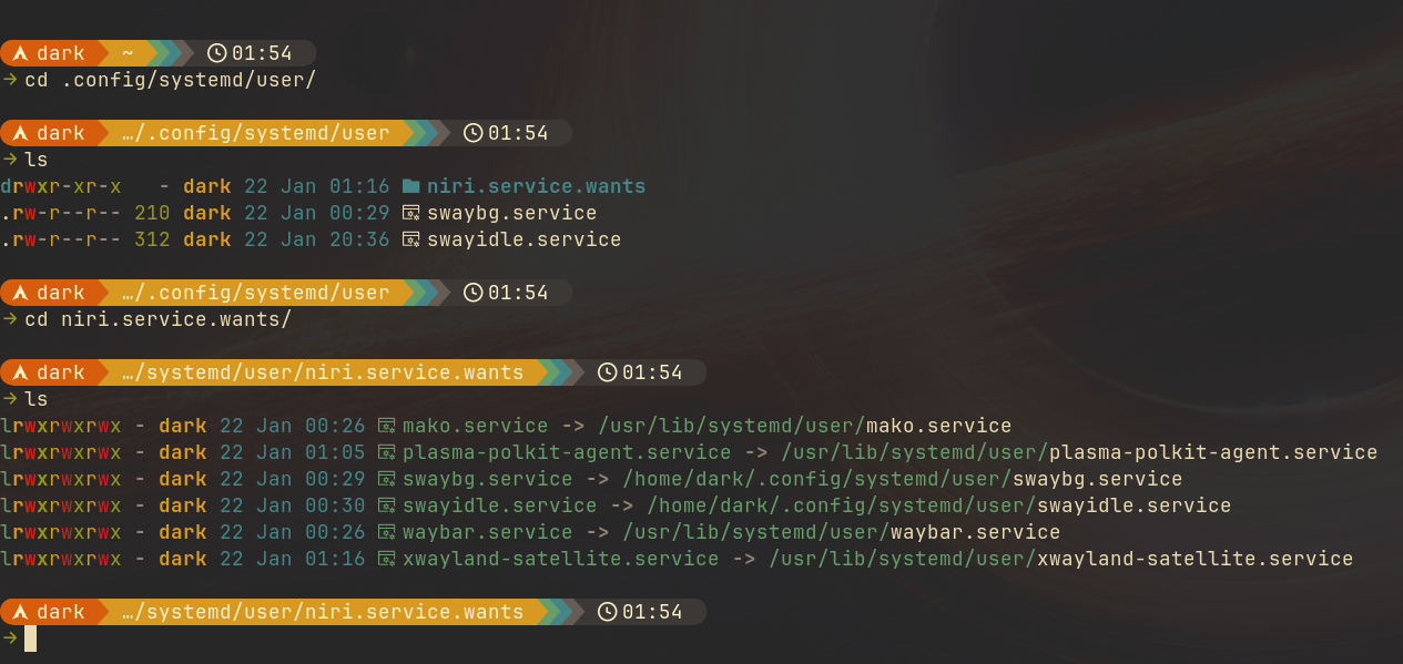
 As we're running a bunch of independent software here with no desktop
environment glueing the parts together we'll use a systemd (go away haters!)
user session to keep everything running:
</p>
<ol>
<li>
  Create the systemd user directory if not existing:
  <code>
   mkdir ~/.config/systemd/user
  </code>
</li>
<li>
  We're running the niri session as a systemd service, so we're putting
everything we want to run into the
  <code>
   niri.service.wants
  </code>
  directory so
it does not interfere with other desktops we may have installed in parallel.
 </li>
<li>
  To be able to use niri on a basic level we're just linking
  <code>
   waybar
  </code>
  in for
now:
  <code>
   ln -s /usr/lib/systemd/user/waybar.service waybar.service
  </code>
</li>
<li>
  Install niri, on Arch it's just
  <code>
   sudo pacman -S niri waybar
  </code>
  to get those
two packets.
 </li>
<li>
  To be able to run something on your session make sure to have at least one
of
  <code>
   Alacritty
  </code>
  or
  <code>
   Fuzzel
  </code>
  installed.
 </li>
</ol>
<p>
 The default configuration of niri has
 <code>
  Mod+T
 </code>
 bound to run Alacritty and
 <code>
  Mod+D
 </code>
 to run Fuzzel.
</p>
<p>
 Go on, log into the niri session now an get yourself a Terminal by pressing
 <code>
  Super+T
 </code>
 (if you're new to this,
 <em>
  Super
 </em>
 is usually the
 <em>
  Windows
 </em>
 key).
 <details>
<summary>
   First segment of
   <code>
    .config/niri/config.kdl
   </code>
   :
  </summary>
<p>
</p>
<p>
<pre><code>input {
    keyboard {
        xkb {
            layout "us(mac)"
        }
    }
    touchpad {
        tap
        natural-scroll
    }
    mouse {
    }
}
</code></pre>
</p>
</details>
</p>
<p>
 The snippet on top defines my keyboard layout to the US Macintosh variant. I
prefer the Mac variants because they have useful combining characters on 
the
 <code>
  Right Alt
 </code>
 layer like
 <code>
  Right Alt+u
 </code>
 for Umlauts and other useful stuff.
</p>
<p>
 See the niri documentation on what else is possible.
 <details>
<summary>
   Segment of
   <code>
    .config/niri/config.kdl
   </code>
   :
  </summary>
<p>
</p>
<p>
<pre><code>layout {
    gaps 8
    center-focused-column "never"

    preset-column-widths {
        proportion 0.33333
        proportion 0.5
        proportion 0.66667
    }

    default-column-width { proportion 0.5; }

    focus-ring {
        off
    }

    border {
        off
    }

    struts {
    }
}
</code></pre>
</p>
</details>
</p>
<p>
 This part basically defines how the window layout works, I completely
deactivated any focus ring or borders as I am using the
 <em>
  waybar
 </em>
 for that and
like a clean look.
 <details>
<summary>
   Segment of
   <code>
    .config/niri/config.kdl
   </code>
   :
  </summary>
<p>
</p>
<p>
<pre><code>prefer-no-csd
screenshot-path "~/Pictures/Screenshots/Screenshot from %Y-%m-%d %H-%M-%S.png"
</code></pre>
</p>
</details>
</p>
<p>
 As said, I like it clean and as we're managing our windows with the keyboard I
want the applications to rely on server side decorations (there are none though).
 <details>
<summary>
   Segment of
   <code>
    .config/niri/config.kdl
   </code>
   :
  </summary>
<p>
</p>
<p>
<pre><code>binds {
    Mod+T { spawn "alacritty"; }
    Mod+Space { spawn "fuzzel"; }
    Mod+B { spawn "firefox"; }

    XF86AudioRaiseVolume allow-when-locked=true { spawn "wpctl" "set-volume" "@DEFAULT_AUDIO_SINK@" "0.1+"; }
    XF86AudioLowerVolume allow-when-locked=true { spawn "wpctl" "set-volume" "@DEFAULT_AUDIO_SINK@" "0.1-"; }
    XF86AudioMute        allow-when-locked=true { spawn "wpctl" "set-mute" "@DEFAULT_AUDIO_SINK@" "toggle"; }
    XF86AudioMicMute     allow-when-locked=true { spawn "wpctl" "set-mute" "@DEFAULT_AUDIO_SOURCE@" "toggle"; }

    XF86MonBrightnessUp allow-when-locked=true { spawn "brightnessctl" "s" "+5"; }
    XF86MonBrightnessDown allow-when-locked=true { spawn "brightnessctl" "s" "5-"; }
}
</code></pre>
</p>
</details>
</p>
<p>
 I am only showing some of the keybinds here because the rest of them are
basically on default settings or are custom to you, but the important ones:
</p>
<ul>
<li>
  The first section are shortcuts that run applications, I am using
  <em>
   Alacritty
  </em>
  ,
  <em>
   Fuzzel
  </em>
  and
  <em>
   Firefox
  </em>
</li>
<li>
  For the multimedia keys I use the command line tool for Wireplumber
  <code>
   wpctl
  </code>
</li>
<li>
  For screen brightness I use
  <code>
   brightnessctl
  </code>
</li>
</ul>
<p>
 You will not have any fancy popups for displaying volume or brightness but
I'll handle that in the waybar configuration.
 <details>
<summary>
   Segment of
   <code>
    .config/niri/config.kdl
   </code>
   :
  </summary>
<p>
</p>
<p>
<pre><code>environment {
    DISPLAY ":1"
}
</code></pre>
</p>
</details>
</p>
<p>
 I am setting the
 <code>
  DISPLAY
 </code>
 env variable here to
 <code>
  :1
 </code>
 to be able to run
XWayland applications.
 <code>
  :0
 </code>
 is already in use by
 <em>
  SDDM
 </em>
 so we have to use
display one here. This may be fragile if you log in multiple times, but I am
not planning to.
 <details>
<summary>
   Segment of
   <code>
    .config/niri/config.kdl
   </code>
   :
  </summary>
<p>
</p>
<p>
<pre><code>workspace "terminal"
workspace "browser"
workspace "chat"

window-rule {
    geometry-corner-radius 6
    clip-to-geometry true
}

window-rule {
    match app-id="Alacritty"
    open-on-workspace "terminal"
}

window-rule {
    match app-id=r#"firefox$"#
    open-on-workspace "browser"
    open-maximized true
}

window-rule {
    match app-id=r#"firefox$"# title="^Picture-in-Picture$"
    open-floating true
    open-maximized false
}

window-rule {
    match app-id="org.telegram.desktop"
    open-on-workspace "chat"
}

window-rule {
    match app-id="org.kde.tokodon"
    open-on-workspace "chat"
}
</code></pre>
</p>
</details>
</p>
<p>
 Lastly I define three named workspaces and put some windows on them by
default. Additionally I am maximizing
 <em>
  Firefox
 </em>
 and making sure the picture
in picture window will be floating and not integrated into the tiles.
</p>
<p>
 That's it, this is my niri config. Niri will reload its configuration after
you change something, so you can try it live.
</p>
<p>
 If you need to find an App ID for window rule matching run this command and
switch to the window in question quickly (you have 3 seconds ;) ):
</p>
<pre><code>sleep 3 ; niri msg focused-window
</code></pre>
<h3 id="waybar-it-has-to-be-configured">
 Waybar... It has to be configured
</h3>
<p>
 The next big chunk of configuration is for
 <em>
  waybar
 </em>
 . The cool thing: it's very
flexible. The bad thing: it's very flexible.
</p>
<p>
 The default config sucks by the way, so go on overwrite it with something that
makes more sense:
</p>
<h4 id="module-config">
 Module config
</h4>
<p>
 Be aware: It is possible that your browser does not display all symbols in
the following config. They are from the Nerdfont installed on my computer,
but I am not including that currently in my CSS here.
 <details>
<summary>
   First part of:
   <code>
    ~/.config/waybar/config.jsonc
   </code>
</summary>
<p>
</p>
<p>
<pre><code>{
    "position": "top",
    "height": 24,
    "spacing": 4,
    "modules-left": [
        "niri/workspaces",
        "niri/window"
    ],
    "modules-center": [
    ],
    "modules-right": [
        "mpris",
        "idle_inhibitor",
        "network",
        "power-profiles-daemon",
        "backlight",
        "wireplumber",
        "bluetooth",
        "battery",
        "tray",
        "clock"
    ]
}
</code></pre>
</p>
</details>
</p>
<p>
 Base config:
</p>
<ul>
<li>
  Show the bar on top
 </li>
<li>
  Define size
 </li>
<li>
  Define loaded modules
 </li>
</ul>
<p>
 To get a list of modules run
 <code>
  man waybar
 </code>
 and scroll down. To get
documentation for a module config run
 <code>
  man waybar-&amp;lt;module&amp;gt;
 </code>
 .
</p>
<p>
 I am using:
</p>
<ul>
<li>
  The workspace switcher
 </li>
<li>
  Current window title
 </li>
<li>
  Media playback icon
 </li>
<li>
  Screensaver deactivator
 </li>
<li>
  Network info
 </li>
<li>
  Power profile
 </li>
<li>
  Backlight
 </li>
<li>
  Audio volume
 </li>
<li>
  Bluetooth status
 </li>
<li>
  Battery status
 </li>
<li>
  System tray
 </li>
<li>
  Clock
 </li>
</ul>
<p>
<img alt="Screenshot workspace switcher " class="center" src="https://dunkelstern.de/articles/2025-01-24/waybar_workspace.png"/>
<details>
<summary>
   Configuration segment for workspace switcher
  </summary>
<p>
</p>
<p>
<pre><code>"niri/workspaces": {
    "format": "{icon}",
    "format-icons": {
        "chat": "\udb82\udf79",
        "browser": "\udb81\udd9f",
        "terminal": "\ue795"
    }
},
</code></pre>
</p>
</details>
</p>
<p>
 Set up workspace switcher. To save space use Icons for the named workspaces.

</p>
<p>
<img alt="Screenshot window title bar" class="center" src="https://dunkelstern.de/articles/2025-01-24/waybar_windowtitle.png"/>
<details>
<summary>
   Configuration segment for window title
  </summary>
<p>
</p>
<p>
<pre><code>"niri/window": {
    "format": "{title}",
    "icon": true,
    "icon-size": 20,
    "rewrite": {
    }
},
</code></pre>
</p>
</details>
</p>
<p>
 Current window title, show the app icon and title. If you want you can
set up
 <em>
  rewrite
 </em>
 rules to rename windows that have awkward titles.

</p>
<p>
<img alt="Screenshot multimedia playback" class="center" src="https://dunkelstern.de/articles/2025-01-24/waybar_mpris.png"/>
<details>
<summary>
   Configuration segment for multimedia playback
  </summary>
<p>
</p>
<p>
<pre><code>"mpris": {
    "format": "\uf144 {status}",
    "tooltip-format": "{player}"
}
</code></pre>
</p>
</details>
</p>
<p>
 Multimedia playback icon, show player in tooltip.

</p>
<p>
<img alt="Screenshot idle inhibitor " class="center" src="https://dunkelstern.de/articles/2025-01-24/waybar_inhibit.png"/>
<details>
<summary>
   Configuration segment for idle inhibitor
  </summary>
<p>
</p>
<p>
<pre><code>"idle_inhibitor": {
    "format": "{icon}",
    "format-icons": {
        "activated": "",
        "deactivated": ""
    }
},
</code></pre>
</p>
</details>
</p>
<p>
 Idle inhibitor: Just disables the automatic screen locking on click

</p>
<p>
<img alt="Screenshot network" class="center" src="https://dunkelstern.de/articles/2025-01-24/waybar_network.png"/>
<details>
<summary>
   Configuration segment for network
  </summary>
<p>
</p>
<p>
<pre><code>"network": {
    "format-wifi": "{essid} ({signalStrength}%) ",
    "format-ethernet": "{ipaddr}/{cidr} ",
    "tooltip-format": "{ifname} via {gwaddr} ",
    "format-linked": "{ifname} (No IP) ",
    "format-disconnected": "Disconnected ⚠",
    "format-alt": "{ifname}: {ipaddr}/{cidr}"
},
</code></pre>
</p>
</details>
</p>
<p>
 Network info, show SSID when on wifi and IP address on wired.
The
 <em>
  alt
 </em>
 format shows up on click.
</p>
<p>
<img alt="Screenshot power profile" class="center" src="https://dunkelstern.de/articles/2025-01-24/waybar_powerprofile.png"/>
<details>
<summary>
   Configuration segment for power profile
  </summary>
<p>
</p>
<p>
<pre><code>"power-profiles-daemon": {
    "format": "{icon}",
    "tooltip-format": "Power profile: {profile}\nDriver: {driver}",
    "tooltip": true,
    "format-icons": {
        "default": "",
        "performance": "",
        "balanced": "",
        "power-saver": ""
    }
},
</code></pre>
</p>
</details>
</p>
<p>
 Power profile switcher: Just set some icons
</p>
<p>
<img alt="Screenshot backlight" class="center" src="https://dunkelstern.de/articles/2025-01-24/waybar_backlight.png"/>
<details>
<summary>
   Configuration segment for backlight
  </summary>
<p>
</p>
<p>
<pre><code>"backlight": {
    "format": "{percent}% {icon}",
    "format-icons": ["", "", "", "", "", "", "", "", ""],
    "on-scroll-down": "brightnessctl s +5",
    "on-scroll-up": "brightnessctl s 5-"
},
</code></pre>
</p>
</details>
</p>
<p>
 Backlight control: reacts to scrolling to increase and decrease screen
brightness.

</p>
<p>
<img alt="Screenshot audio" class="center" src="https://dunkelstern.de/articles/2025-01-24/waybar_audio.png"/>
<details>
<summary>
   Configuration segment for audio
  </summary>
<p>
</p>
<p>
<pre><code>"wireplumber": {
    "format": "{volume}% {icon}",
    "format-muted": "Muted  ",
    "format-icons": {
        "headphone": "",
        "hands-free": "",
        "headset": "",
        "phone": "",
        "portable": "",
        "car": "",
        "default": ["", "", ""]
    },
    "min-length": 10,
    "on-click": "pwvucontrol",
    "on-click-right": "wpctl set-mute @DEFAULT_AUDIO_SINK@ toggle",
    "on-scroll-up": "wpctl set-volume @DEFAULT_AUDIO_SINK@ 5%-",
    "on-scroll-down": "wpctl set-volume @DEFAULT_AUDIO_SINK@ 5%+"
},
</code></pre>
</p>
</details>
</p>
<p>
 Audio volume, set some icons and run
 <code>
  pwvucontrol
 </code>
 when clicking,
right click mutes/unmutes and scrollwheel changes volume
</p>
<p>
<img alt="Screenshot bluetooth" class="center" src="https://dunkelstern.de/articles/2025-01-24/waybar_bluetooth.png"/>
<details>
<summary>
   Configuration segment for bluetooth
  </summary>
<p>
</p>
<p>
<pre><code>"bluetooth": {
    "format-on": "\udb80\udcaf ON",
    "format-off": "\udb80\udcb2 OFF",
    "format-connected": "\udb80\udcb1 {device_alias}",
    "on-click": "overskride",
    "on-click-right": "bluetoothctl power $(bluetoothctl show | grep -q \"Powered: yes\" &amp;&amp; echo off || echo on)",
    "min-length": 8
    },
</code></pre>
</p>
</details>
</p>
<p>
 Bluetooth module:
</p>
<ul>
<li>
  Just a bluetooth icon and the most recently connected device.
 </li>
<li>
  On click run
  <code>
   Overskride
  </code>
  to configure bluetooth
 </li>
<li>
  On right click toggle Bluetooth power
 </li>
</ul>
<p>
<img alt="Screenshot battery" class="center" src="https://dunkelstern.de/articles/2025-01-24/waybar_battery.png"/>
<details>
<summary>
   Configuration segment for battery
  </summary>
<p>
</p>
<p>
<pre><code>"battery": {
    "states": {
        "warning": 30,
        "critical": 15
    },
    "format": "{capacity}% {icon}",
    "format-full": "{capacity}% {icon}",
    "format-charging": "{capacity}% ",
    "format-plugged": "{capacity}% ",
    "format-alt": "{time} {icon}",
    "format-icons": ["", "", "", "", ""],
"min-length": 10
},
</code></pre>
</p>
</details>
</p>
<p>
 Battery status, set some thresholds and icons.

</p>
<p>
<img alt="Screenshot systray" class="center" src="https://dunkelstern.de/articles/2025-01-24/waybar_systray.png"/>
<details>
<summary>
   Configuration segment for systray
  </summary>
<p>
</p>
<p>
<pre><code>"tray": {
    "icon-size": 20,
    "spacing": 10
},
</code></pre>
</p>
</details>
</p>
<p>
 System tray: just set geometry
</p>
<p>
<img alt="Screenshot clock" class="center" src="https://dunkelstern.de/articles/2025-01-24/waybar_clock.png"/>
<details>
<summary>
   Configuration segment for clock
  </summary>
<p>
</p>
<p>
<pre><code>"clock": {
    "tooltip-format": "&lt;big&gt;{:%Y %B}&lt;/big&gt;\n&lt;tt&gt;&lt;small&gt;{calendar}&lt;/small&gt;&lt;/tt&gt;",
    "format-alt": "{:%Y-%m-%d}"
},
</code></pre>
</p>
</details>
</p>
<p>
 Set format for the clock
</p>
<h4 id="theme">
 Theme
</h4>
<p>
 The theme is based on gruvbox colors and is stored
in:
 <code>
  ~/.config/waybar/style.css
 </code>
<details>
<summary>
   Theme CSS file
  </summary>
<p>
</p>
<p>
<pre><code>* {
    /* `otf-font-awesome` is required to be installed for icons */
    font-family: FontAwesome, Cantarell, sans-serif;
    font-size: 13px;
}

window#waybar {
    background-color: rgba(40, 40, 40, 0.75);
    color: #ffffff;
    transition-property: background-color;
    transition-duration: .5s;
}

window#waybar.hidden {
    opacity: 0.2;
}

button {
    /* Use box-shadow instead of border so the text isn't offset */
    box-shadow: inset 0 -3px transparent;
    /* Avoid rounded borders under each button name */
    border: none;
    border-radius: 0;
}

/* https://github.com/Alexays/Waybar/wiki/FAQ#the-workspace-buttons-have-a-strange-hover-effect */
button:hover {
    background: inherit;
    box-shadow: inset 0 -3px #ffffff;
}

/* you can set a style on hover for any module like this */
#wireplumber:hover {
    background-color: #a37800;
}

#workspaces button {
    padding: 0 5px;
    background-color: transparent;
    color: #ffffff;
}

#workspaces button:hover {
    background: rgba(0, 0, 0, 0.2);
}

#workspaces button.focused {
    background-color: #64727D;
    box-shadow: inset 0 -3px #ffffff;
}

#workspaces button.urgent {
    background-color: #eb4d4b;
}

#mode {
    background-color: #64727D;
    box-shadow: inset 0 -3px #ffffff;
}

#clock,
#battery,
#cpu,
#memory,
#disk,
#temperature,
#backlight,
#network,
#pulseaudio,
#wireplumber,
#custom-media,
#tray,
#mode,
#idle_inhibitor,
#scratchpad,
#power-profiles-daemon,
#mpd {
    padding: 0 10px;
    color: #ffffff;
}

#window,
#workspaces {
    margin: 0 10px;
}

/* If workspaces is the leftmost module, omit left margin */
.modules-left &gt; widget:first-child &gt; #workspaces {
    margin-left: 0;
}

/* If workspaces is the rightmost module, omit right margin */
.modules-right &gt; widget:last-child &gt; #workspaces {
    margin-right: 0;
}

#clock {
    background-color: #282828;
    color: #fbf1c7;
}

#tray {
    background-color: #504945;
    color: #fbf1c7;
}

#battery {
    background-color: #458588;
    color: #3c3836;
}

#battery.charging, #battery.plugged, #battery.not-charging {
    color: #fbf1c7;
    background-color: #458588;
}

@keyframes blink {
    to {
        background-color: #cc241d;
        color: #fbf1c7;
    }
}

/* Using steps() instead of linear as a timing function to limit cpu usage */
#battery.critical:not(.charging) {
    background-color: #458588;
    color: #fbf1c7;
    animation-name: blink;
    animation-duration: 0.5s;
    animation-timing-function: steps(5);
    animation-iteration-count: infinite;
    animation-direction: alternate;
}

#bluetooth {
    color: #3c3836;
    background-color: #98971a;
}

label:focus {
    background-color: #000000;
}

#wireplumber {
    background-color: #d79921;
    color: #3c3836;
}

#wireplumber.muted {
    background-color: #d65d0e;
}

#backlight {
    background-color: #d65d0e;
    color: #3c3836;
}

#power-profiles-daemon {
    padding-right: 15px;
    background-color: #cc241d;
    color: #3c3836;
}

#network {
    background-color: #b16286;
    color: #3c3836;
}

#tray &gt; .passive {
    -gtk-icon-effect: dim;
}

#tray &gt; .needs-attention {
    -gtk-icon-effect: highlight;
    background-color: #eb4d4b;
}

#idle_inhibitor {
    background-color: #2d3436;
}

#idle_inhibitor.activated {
    background-color: #ecf0f1;
    color: #2d3436;
}
</code></pre>
</p>
</details>
</p>
<h3 id="fuzzel-a-launcher-that-just-works">
 Fuzzel: a launcher that just works
</h3>
<p>
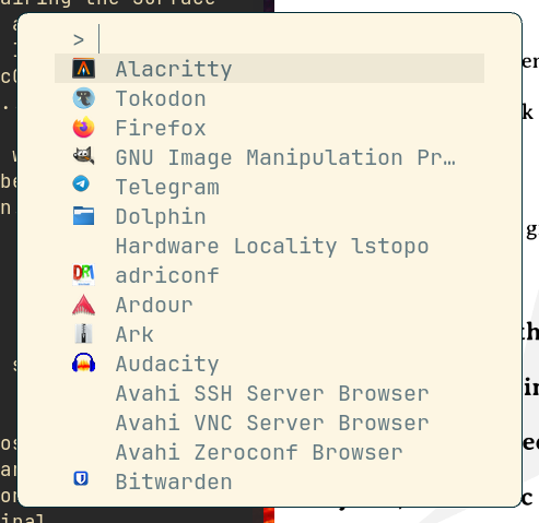
 Fuzzel is a very simple program, when it opens it gives you a list
of all
 <code>
  *.desktop
 </code>
 files it finds and you can fuzzy search for an application
and run it.
</p>
<p>
<img alt="Screenshot of Fuzzel running" class="center" src="https://dunkelstern.de/articles/2025-01-24/fuzzel.png"/>
</p>
<p>
 You can configure the font it's using, the position, shortcuts to run
something directly from the list without using the search etc.
</p>
<p>
 It has another function though; you can feed a list of options to it and it
just echoes the selected entry back to
 <code>
  stdout
 </code>
 for usage in scripts.
</p>
<p>
 The following snippet for example shows a menu with one entry in it: "Firefox"
</p>
<pre><code>echo -en "Firefox\0icon\x1ffirefox" | fuzzel --dmenu
</code></pre>
<p>
 I just set the font to
 <em>
  JetBrains Mono
 </em>
 in
 <code>
  ~/.config/fuzzel/fuzzel.ini
 </code>
 :
</p>
<pre><code>font="JetBrains Mono"
</code></pre>
<h3 id="alacritty-fast-terminal">
 Alacritty: fast terminal
</h3>
<p>
<img alt="Screenshot of alacritty with starship prompt" class="center" src="https://dunkelstern.de/articles/2025-01-24/alacritty.jpg"/>
</p>
<p>
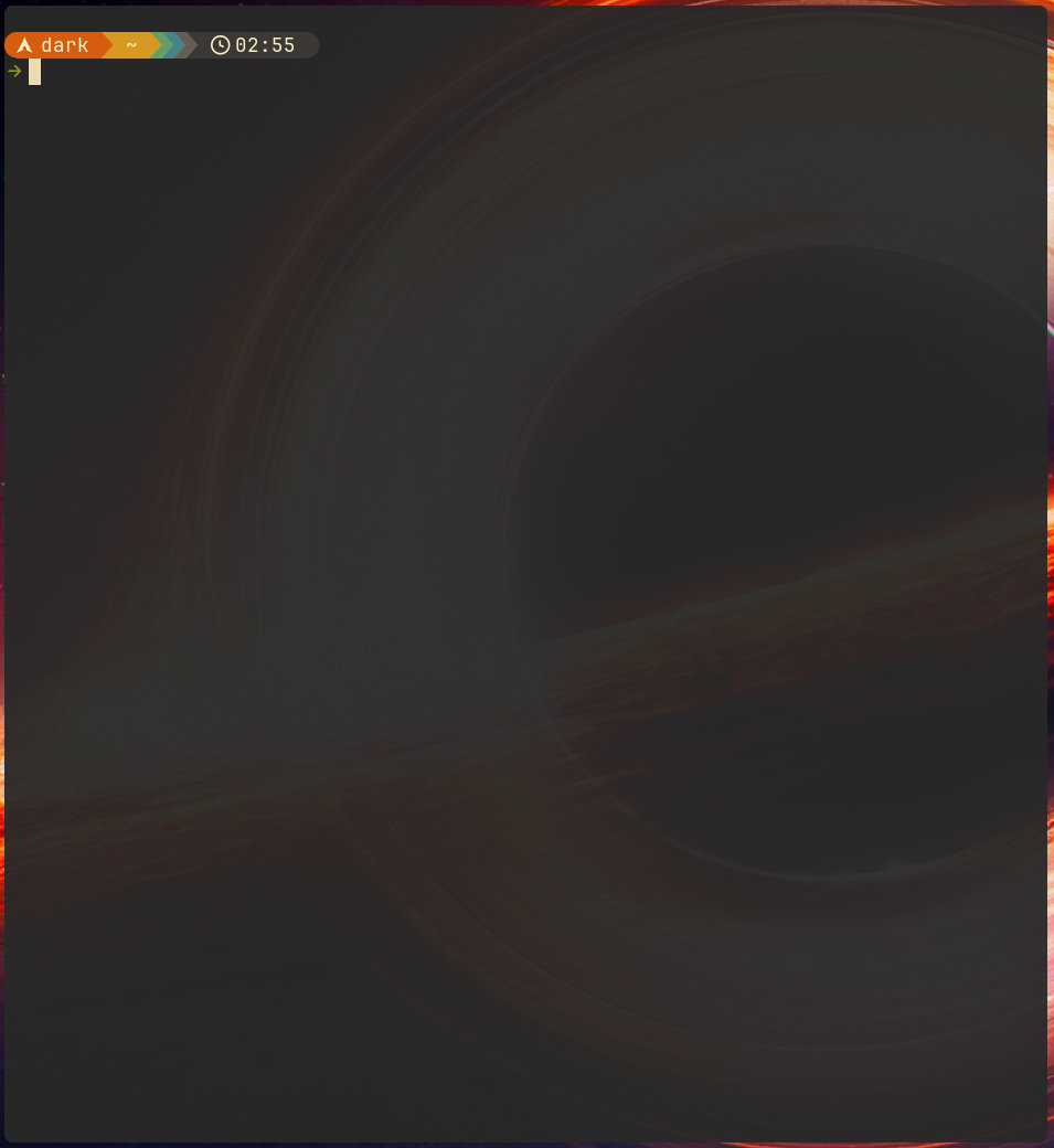
 Alacritty is a fast OpenGL accelerated terminal. I configured the theme to
gruvbox:
 <details>
<summary>
   Alacritty config in
   <code>
    ~/.config/alacritty
   </code>
</summary>
<p>
</p>
<p>
<pre><code>[general]
live_config_reload = true
import = [ "~/.config/alacritty/gruvbox.toml" ]

[window]
opacity = 0.95

[scrolling]
history = 10000

[font]
normal = { family = "JetbrainsMonoNL Nerd Font", style = "Regular" }
size = 10.5
builtin_box_drawing = false

[bell]
animation = "Ease"
duration = 100
color = "#3c3836"

[selection]
save_to_clipboard = true

[cursor]
style = { shape = "Block", blinking = "On" }
blink_interval = 333

[mouse]
hide_when_typing = true
</code></pre>
</p>
</details>
</p>
<p>
 The settings you can set here are pretty basic:
</p>
<ul>
<li>
  Window transparency
 </li>
<li>
  Scrollback buffer (10000 for me)
 </li>
<li>
  Font
 </li>
<li>
  Visual bell instead of beeping
 </li>
<li>
  Save selections to clipboard
 </li>
<li>
  Make the cursor blink and
 </li>
<li>
  the mouse disappear when typing
 </li>
</ul>
<p>
 I am importing the theme from an additional theme file:
 <details>
<summary>
   Theme file
  </summary>
<p>
</p>
<p>
<pre><code>[colors.primary]
background = "#282828"
# soft contrast:
#  background = "#32302f"
foreground = "#ebdbb2"

[colors.normal]
black = "#282828"
red = "#cc241d"
green = "#98971a"
yellow = "#d79921"
blue = "#458588"
magenta = "#b16286"
cyan = "#689d6a"
white = "#a89984"

[colors.bright]
black = "#928374"
red = "#fb4934"
green = "#b8bb26"
yellow = "#fabd2f"
blue = "#83a598"
magenta = "#d3869b"
cyan = "#8ec07c"
white = "#ebdbb2"
</code></pre>
</p>
</details>
</p>
<p>
 But just the terminal color settings is not enough to feel good. I could go
to more lengths for my vim configuration but that will be probably another
blog entry as I have to explain how to use those modules in detail. So
watch this place.
</p>
<p>
 One simple thing I can tell you: for a fancy prompt install
 <code>
  starship
 </code>
 and
run the following commands to activate it:
</p>
<pre><code>starship preset gruvbox-rainbow &gt;~/.config/starship.toml
starship init bash &gt;&gt; ~/.bashrc
</code></pre>
<p>
 Restart your terminal and be happy about the colorful prompt :)
</p>
<h3 id="mako-to-be-informed">
 Mako to be informed
</h3>
<p>
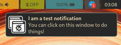
<img alt="Screenshot of a test notification" class="right" src="https://dunkelstern.de/articles/2025-01-24/mako.jpg"/>
</p>
<p>
 Mako will be used to have a notification bubble show up when some application
wants to have your attention. It can do many things but the configuration is
simple:
 <details>
<summary>
   Mako config in
   <code>
    ~/.config/mako/config
   </code>
</summary>
<p>
</p>
<p>
<pre><code>font=Cantarell 10.5
background-color=#282828ff
text-color=#ebdbb2ff
border-size=1
border-color=#83a598ff
border-radius=6
default-timeout=30000
</code></pre>
</p>
</details>
</p>
<p>
 I just set some colors, made the border radius match the one of niri and
configured a font that is actually installed.
</p>
<p>
 But how does the system know that we want to use Mako? On a desktop
environment the desktop manager would carry out that burden, on our Lego
version of assembling a desktop you got to keep the parts.
</p>
<p>
 Let's have systemd handle that for us:
</p>
<pre><code>ln -s \
  /usr/lib/systemd/user/mako.service \
  ~/.config/systemd/user/niri.service.wants/mako.service
</code></pre>
<h3 id="swayidleswaylock-automatic-screen-locking-is-an-app">
 Swayidle/Swaylock, automatic screen locking is an app?
</h3>
<p>
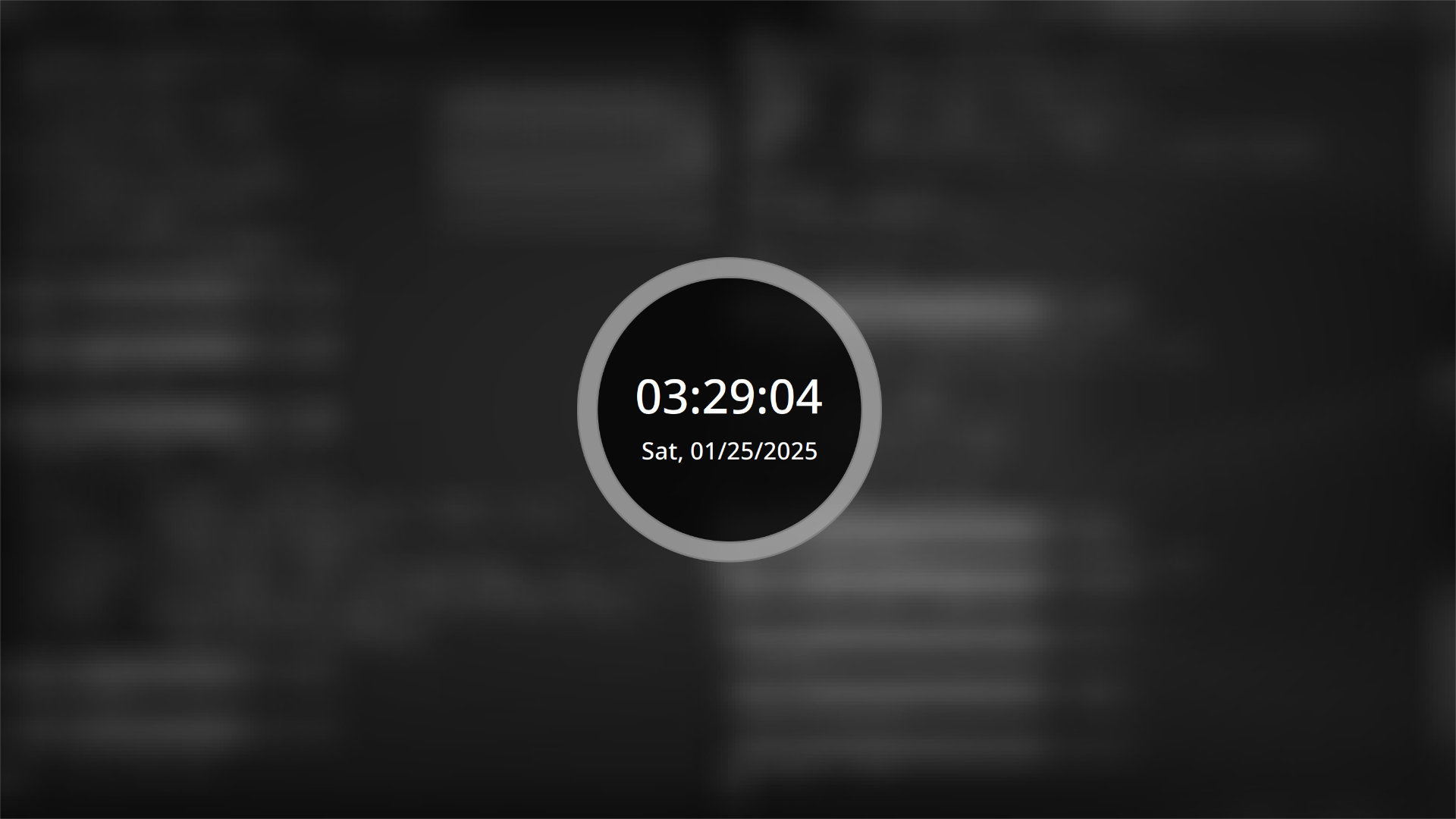
 As already said, you get to keep the parts, not even screen locking or turning
off the screen are handled automatically.
</p>
<p>
<img alt="Swaylock screenshot" class="center" src="https://dunkelstern.de/articles/2025-01-24/swaylock.jpg"/>
</p>
<p>
 As we want to configure how it looks (the default is terrible) we create
another config file.
 <details>
<summary>
   Config file in
   <code>
    ~/.config/swaylock/config
   </code>
</summary>
<p>
</p>
<p>
<pre><code>screenshots
clock
indicator-idle-visible
grace=5
indicator-radius=150
indicator-thickness=20
effect-scale=0.2
effect-blur=5x2
effect-greyscale
effect-scale=5
effect-vignette=0.5:0.5
line-color=808080ff
ring-color=a0a0a0dd
key-hl-color=ffffffff
text-color=ffffffff
ring-ver-color=ffffffff
inside-ver-color=ffffffff
</code></pre>
</p>
</details>
</p>
<p>
 Be aware I am using a fork of a fork of a fork here:
 <code>
  swaylock-effects-improved
 </code>
 , if you don't want to
 <a href="https://aur.archlinux.org/packages/swaylock-effects-improved-git">
  pull it from the AUR
 </a>
 I am afraid you have to compile it yourself.
</p>
<p>
 So that's the lock screen, but nobody calls for it to show up yet, hey you
guessed it... let's use systemd:
 <details>
<summary>
   Service definition in
   <code>
    ~/.config/systemd/user/swayidle.service
   </code>
</summary>
<p>
</p>
<p>
<pre><code>[Unit]
PartOf=graphical-session.target
After=graphical-session.target
Requisite=graphical-session.target

[Service]
ExecStart=/usr/bin/swayidle -w timeout 601 'niri msg action power-off-monitors' timeout 600 '/usr/bin/swaylock' before-sleep '/usr/bin/swaylock'
Restart=on-failure
</code></pre>
</p>
</details>
</p>
<p>
 After creating the file reload systemd:
 <code>
  systemctl --user daemon-reload
 </code>
 and link the thing to niri:
</p>
<pre><code>ln -s \
  ~/.config/systemd/user/swayidle.service \
  ~/.config/systemd/user/niri.service.wants/swayidle.service
</code></pre>
<p>
 If you want to lock your screen with a keyboard shortcut you can add it
to the niri config like this:
</p>
<pre><code>binds {
    Mod+L { spawn "/usr/bin/swaylock"; }
}
</code></pre>
<h3 id="pwvucontrol-pretzel-fingers-while-typing">
 PWVucontrol, pretzel fingers while typing
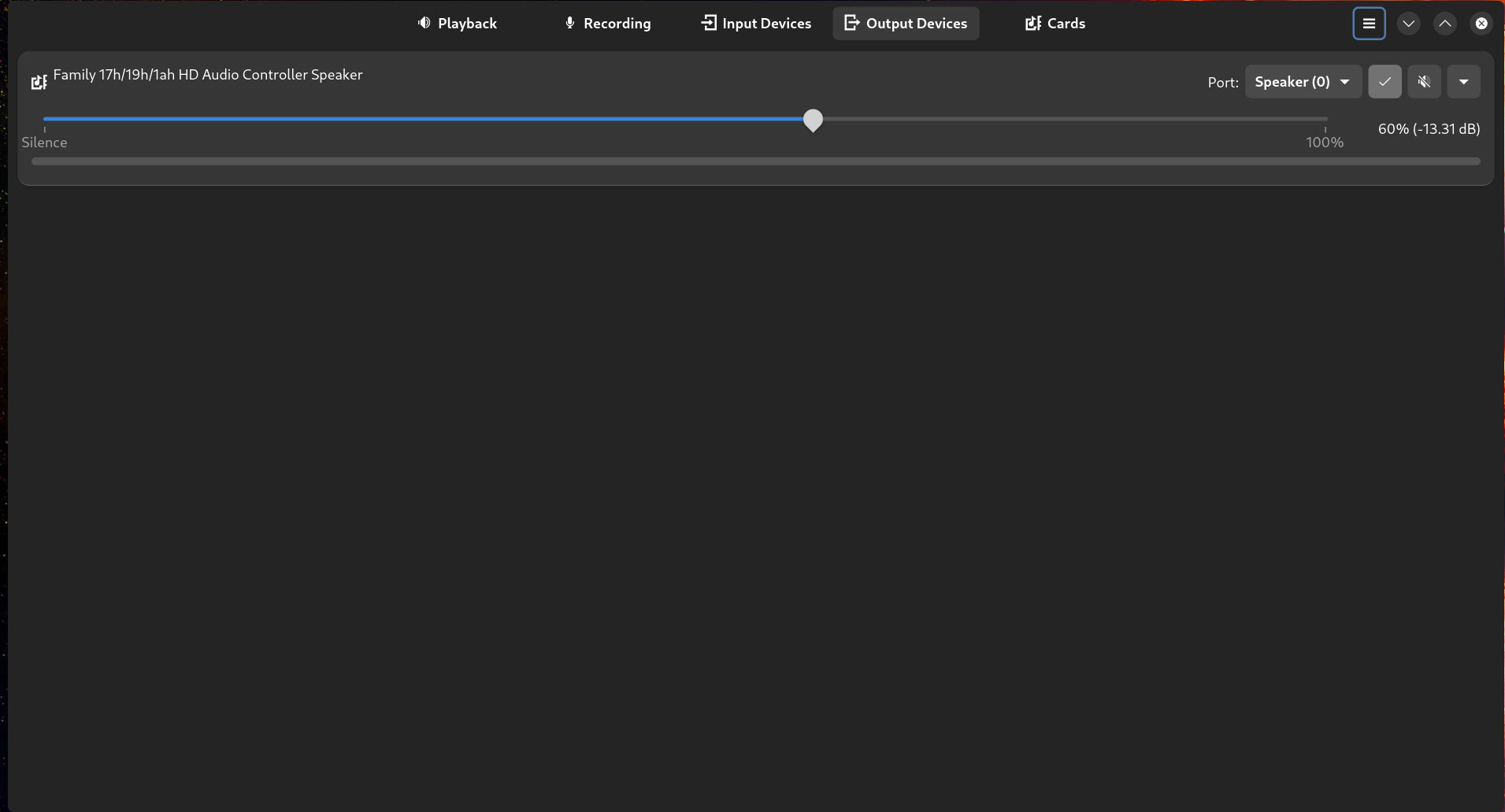
</h3>
<p>
<img alt="Screenshot of pretzel control" class="center" src="https://dunkelstern.de/articles/2025-01-24/pwvucontrol.jpg"/>
</p>
<p>
 You could use
 <code>
  pavucontrol
 </code>
 (another pretzel) to control your audio but
as modern systems use wireplumber in the background and we love to use another
rust application I went for the native pretzel.
</p>
<p>
<a href="https://aur.archlinux.org/packages/pwvucontrol">
  Get it from the AUR
 </a>
 if
you're on Arch or take the meson build in your own hands.
</p>
<p>
 Nothing to configure here, just for completeness sake (you need to control
your audio somehow...)
</p>
<h3 id="overskride-how-did-that-name-happen">
 Overskride, how did that name happen?
</h3>
<p>
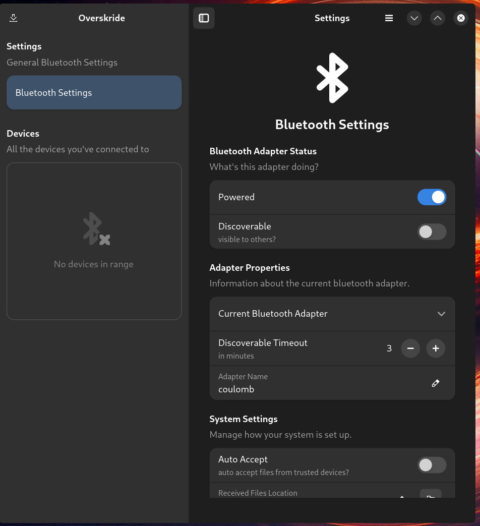
<img alt="Screenshot of Overskride" class="center" src="https://dunkelstern.de/articles/2025-01-24/overskride.jpg"/>
</p>
<p>
 Please tell me, how do you find this application after you installed it and
did not call it by name for half an hour? No, I am waiting...
</p>
<p>
 Another
 <code>
  libadwaita
 </code>
 application, another application written in rust... hey
I am not trying to force using rust applications, it just so happens they are
good mostly!
</p>
<p>
 Nothing to configure here either, but a nice interface to your bluetooth
settings.
</p>
<p>
 Again:
</p>
<ul>
<li>
<a href="https://aur.archlinux.org/packages/overskride">
   AUR
  </a>
</li>
<li>
  Or build it with meson yourself: https://github.com/kaii-lb/overskride
 </li>
</ul>
<h3 id="swaybg-this-reminds-me-of-barebones-x11-in-1999">
 SwayBg, this reminds me of barebones X11 in 1999
</h3>
<p>
 And now for something that absolutely reminds me of the late 90ies and early
2000s... At that time I worked not just with Linux but all kinds of Unix
boxes. We had Solaris, HPUX, AIX and my personal Workstation in my job back
then a SGI Octane with IRIX. Why am I remembered of that? Well the default
background of X11 after startup was a checkered black and white pattern that
really killed you if you had to look at it on a lower resolution monitor.
In addition to that not all window managers were desktop environments and
it seems nobody found it necessary to set a background image on XFree86.
</p>
<p>
 If you used CDE or some kind of desktop environment you basically got a solid
color or some kind of marble texture as a background. But if you experimented
with X11 stuff sometimes you defaulted to a simple window manager which did
not replace the patterned background. There were tools to set a background
image... Wayland with a simple compositor is the same.
</p>
<p>
 I mean at least the background is solid black...
</p>
<p>
 To fix that you have to run a wayland client that basically presents the
background. And you guessed it: something or someone has to start that.
</p>
<p>
 Drumroll... let's use systemd!
 <details>
<summary>
   Systemd service file for swaybg in
   <code>
    ~/.config/systemd/user/swaybg.service
   </code>
</summary>
<p>
</p>
<p>
<pre><code>[Unit]
PartOf=graphical-session.target
After=graphical-session.target
Requisite=graphical-session.target

[Service]
ExecStart=/usr/bin/swaybg -m fill -i "%h/Pictures/Wallpaper/blackhole.jpg"
Restart=on-failure
</code></pre>
</p>
</details>
</p>
<p>
 The
 <code>
  %h
 </code>
 in the
 <code>
  ExecStart
 </code>
 line will be replaced with your home directory.
</p>
<p>
 Finally link the thing to niri:
</p>
<pre><code>ln -s \
  ~/.config/systemd/user/swaybg.service \
  ~/.config/systemd/user/niri.service.wants/swaybg.service
</code></pre>
<h3 id="xwayland-sattelite-to-run-that-software-from-1999-or-gimp">
 Xwayland sattelite to run that software from 1999 (or GIMP)
</h3>
<p>
 As we were at retro things: Lets enable Xwayland for older applications. Niri
does not by default have support for Xwayland, but there's a fix for that:
 <code>
  Xwayland-satellite
 </code>
 . That thing just listens to the X11 display socket and
spawns in windows that render the older X11 apps.
</p>
<p>
 You need to run it, but basically you don't have to configure it.
</p>
<pre><code>ln -s \
  /usr/lib/systemd/user/xwayland-satellite.service \
  ~/.config/systemd/user/niri.service.wants/xwayland-satellite.service
</code></pre>
<p>
 And as you probably have noticed in the niri config: we already set the
 <code>
  DISPLAY
 </code>
 environment variable to
 <code>
  :1
 </code>
 so the applications will find the
emulated X11 server.
</p>
<p>
 Hey it seems you're at the end! Restart your session and test if it works!
</p>
 ]]></content>
  <author>
    <email>hallo@dunkelstern.de</email>
    <name>Johannes Schriewer</name>
  </author>
 </entry>
 
 <entry>
  <title>Fixing the stupid Surface Laptop 3</title>

  <link rel="alternate" type="text/html" href="https://dunkelstern.de/articles/2025-01-19/index.html"/>
  <id>urn:uuid:1dbd4161-6a09-50ee-b2ca-f279eb58ea50</id>
  <published>2025-01-19T00:00:00+01:00</published>
  <updated>2025-01-19T21:23:05+01:00</updated>
  <summary><![CDATA[ <p>
 So it turns out I was really stupid to attest Microsoft any technical prowess in 2020.
</p>
 ]]></summary>
  <content type="html"><![CDATA[ <h2 id="why-microsoft-oh-why">
 Why Microsoft oh why?
</h2>
<p>
 So it turns out I was really stupid to attest Microsoft any technical prowess in 2020.
</p>
<p>
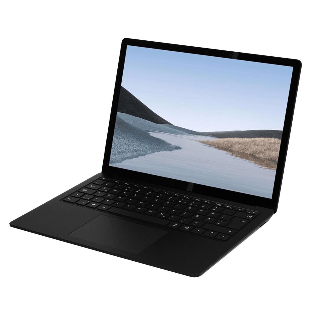
 I bought a Surface Laptop 3 (AMD) in 2020 as it seemed to be a really well built Laptop that
could rival the construction of a MacBook. I did not want to buy a Mac this time around
as it was not clear if you would be able to run Linux on the Apple Silicon Macs ever.
</p>
<p>
<img alt="Surface Laptop 3 promotional image" class="center" src="https://dunkelstern.de/articles/2025-01-19/surface_laptop_3_promo.jpg"/>
</p>
<p>
 In hindsight it turns out you can with
 <a href="https://asahilinux.org/">
  Asahi Linux
 </a>
 ...
</p>
<p>
 The odysee began. First the Audio controller had a hardware bug that lead to Bluescreens
on each and every standby/hibernate cycle. I sent the Laptop back and got a new one.
</p>
<p>
 That one had severe latency problems, when you're using Wifi the audio would stutter
badly. Sent that one back too. The new one had exactly the same problem. Usually I would
have gotten a lawyer and told them to get me my money back at this point, but this was
the year of the big C, so no dice. I switched to a Lenovo Yoga 7 slim and the Surface
Laptop was used by my girlfriend on Linux where the audio stuttering was no problem.
</p>
<p>
 Later on she got the Macbook I should have bought in the first place...
</p>
<p>
 Linux on that laptop is quite a good experience but you won't be able to use the
touchscreen.
</p>
<p>
 Recently I felt the need to be able to run Windows on a machine again for CAD reasons.
Now the audio stuttering annoyed me so much I went for drastic measures.
</p>
<h2 id="the-solution">
 The solution
</h2>
<p>
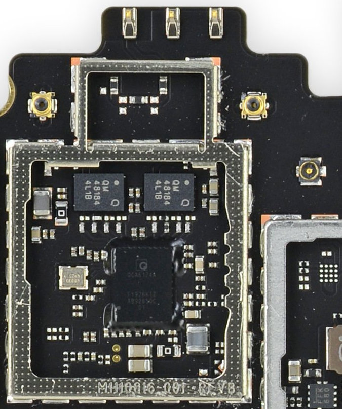
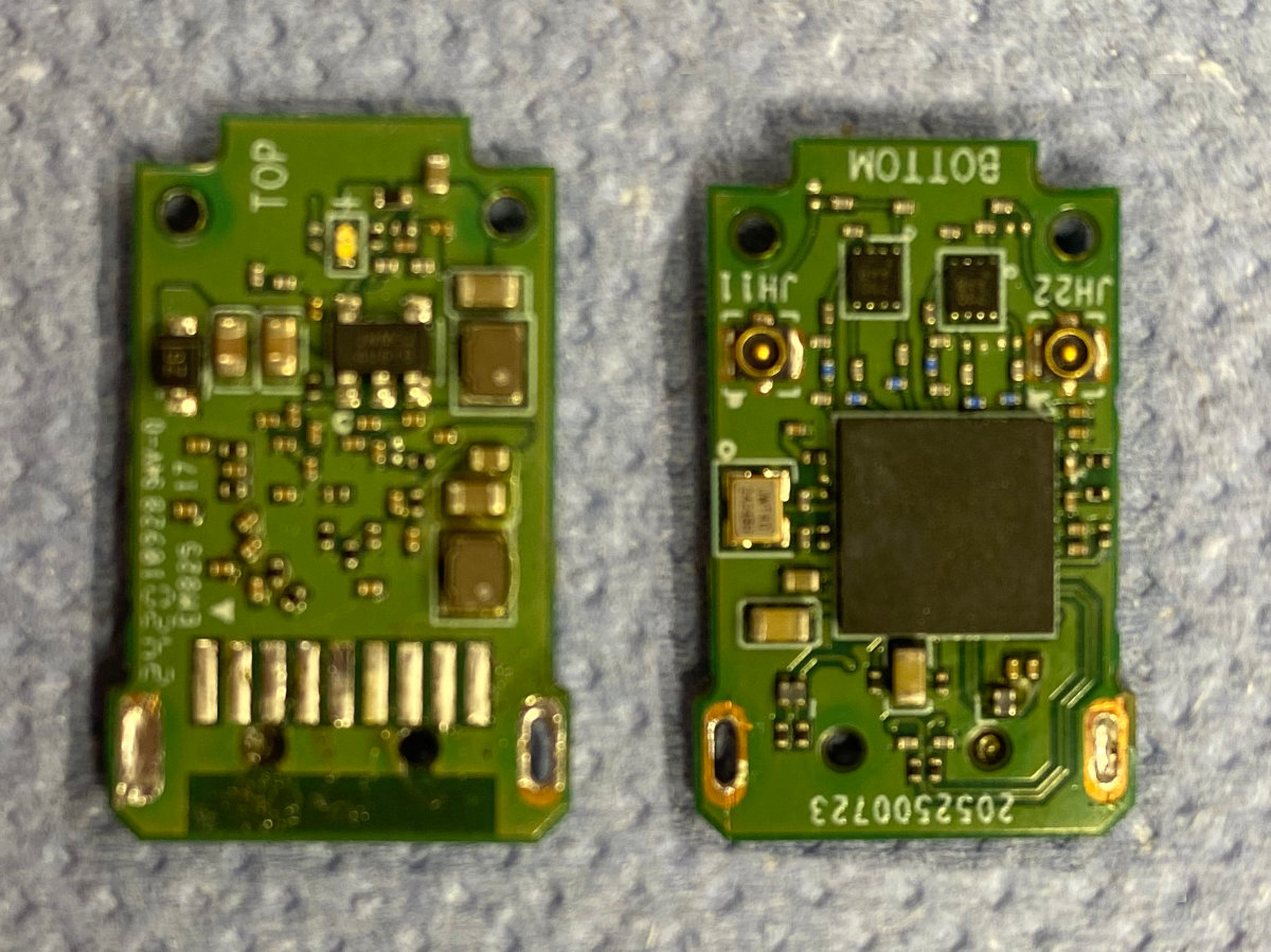
<img alt="Wifi module" class="left" src="https://dunkelstern.de/articles/2025-01-19/wifi_integrated.jpg"/>
</p>
<p>
 So what's causing the audio stuttering on Windows that does not affect Linux on this
Laptop? Simple answer: Bad drivers... for Windows... on a Microsoft built laptop...
</p>
<p>
 Thanks man.
</p>
<p>
 You cannot replace the Wifi module as they decided to integrate that with the Mainboard.
</p>
<p>
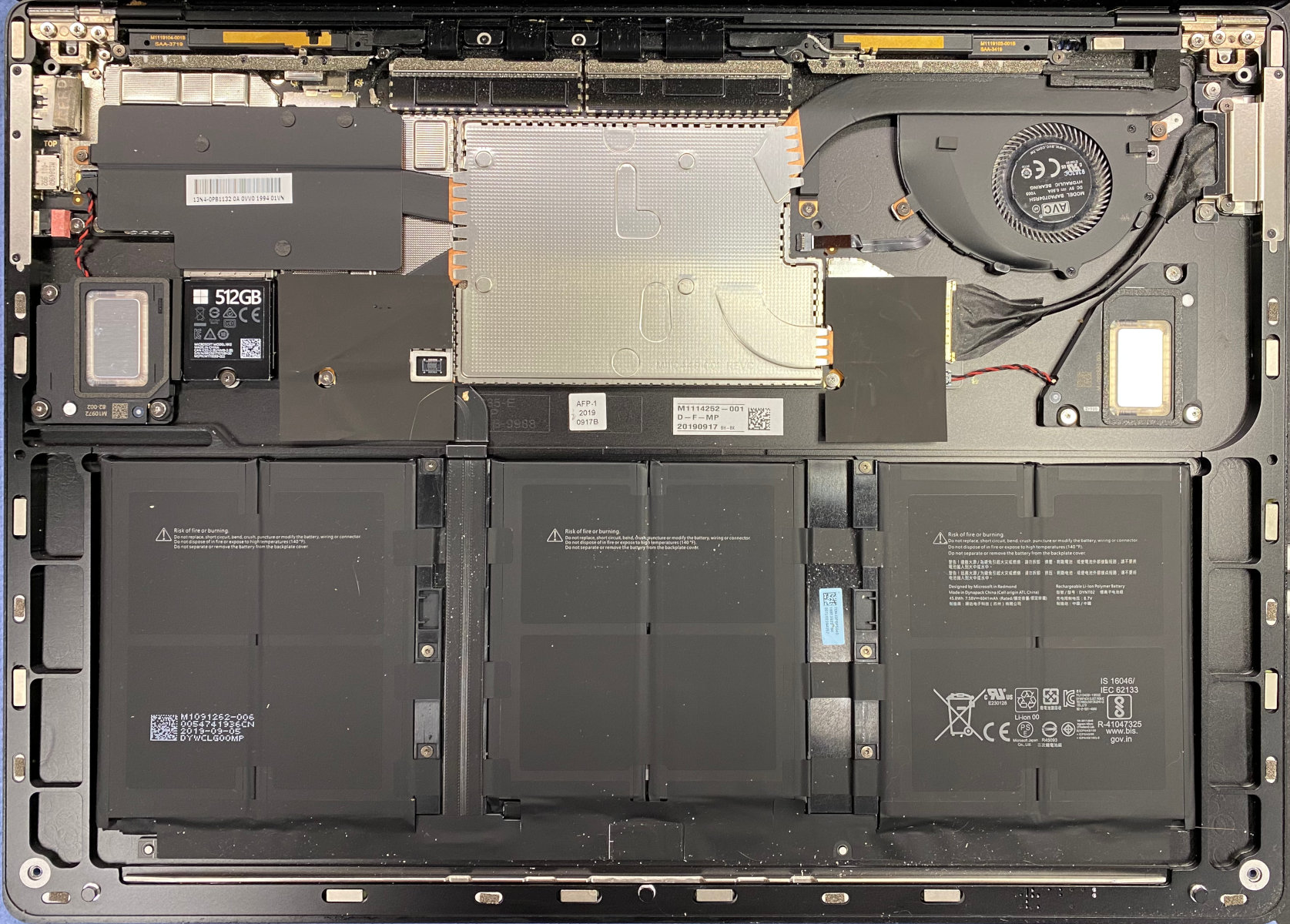
 This laptop can be opened by removing 4 screws and the rest is magnetically attached,
quite nifty, but I have to ask Microsoft: Why? The only thing you can replace is the
SSD (I mean that's better than Apple but still). The Battery is glued in without any
rubberband release strips like Apple does it, the Mainboard contains the soldered RAM...
You can exchange the dock port and the audio jack, but the USB ports are soldered to
the mainboard again, but back to the topic:
</p>
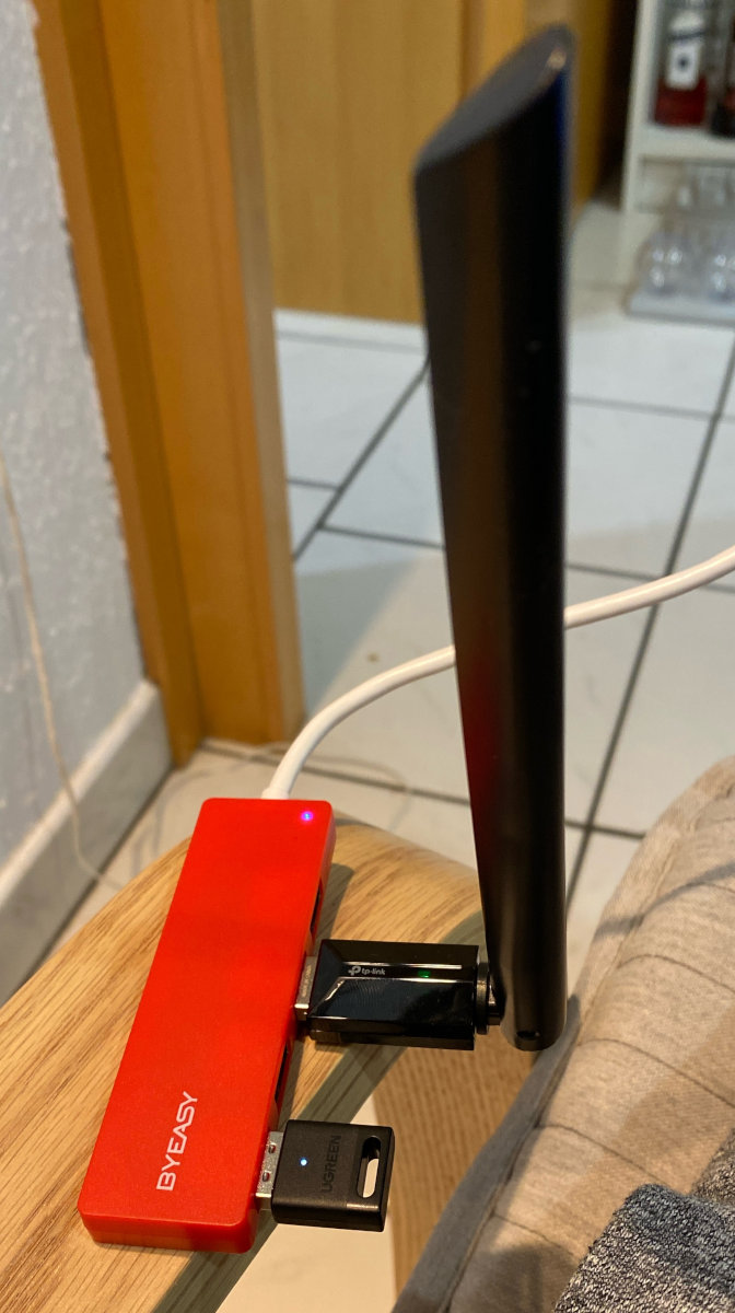
<p>
<img alt="USB hub dangling from the Laptop" class="center" src="https://dunkelstern.de/articles/2025-01-19/hub_dangle.jpg"/>
</p>
<p>
 The solution here is to disable the Qualcomm Wifi and Bluetooth stuff in device manager
and use USB sticks to replace the functionality. As I don't want a USB hub dangling from
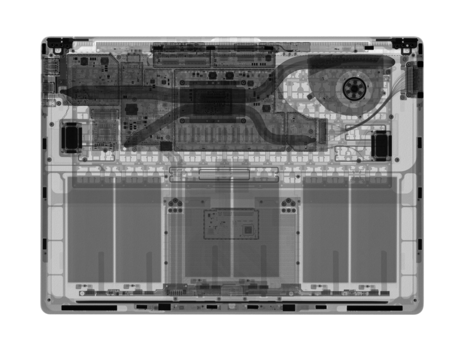
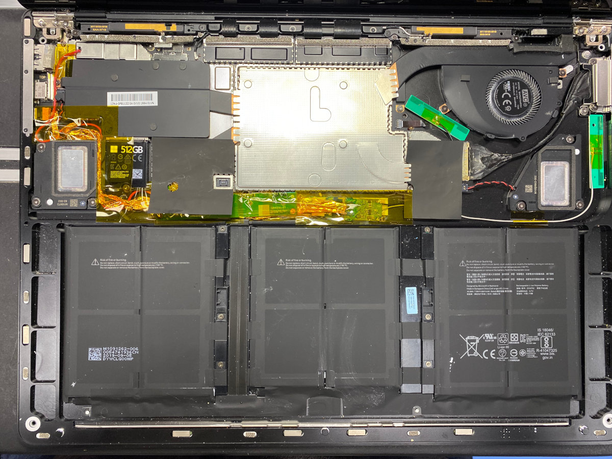
the laptop all the time I investigated if there is space in the case to drop additional
hardware in. Turns out: There is! They did use the mainboard of the 13 inch laptop on the
15 inch, as well as the same battery on both versions so you have quite a lot of space.
</p>
<p>
<img alt="X-Ray image by iFixit" class="center" src="https://dunkelstern.de/articles/2025-01-19/xray.jpg"/>
</p>
<h2 id="reverse-engineering-the-surface-dock-connector">
 Reverse engineering the Surface dock connector
</h2>
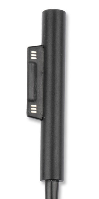
<p>
 What is the Surface Dock connector you ask? Simple, Microsoft
 <s>
  stole
 </s>
 licensed Apples
Magsafe "attached connector via magnets" thing and created a reversible (caveat emptor)
connector that can charge the laptop as well as be a docking port to an external dock
that you can leave on your desk for a simple one cable docking action.
</p>
<p>
<img alt="Surface Dock charging cable" class="right" src="https://dunkelstern.de/articles/2025-01-19/surface_charging_cable.jpg"/>
</p>
<p>
 You can find
 <a href="https://dancharblog.wordpress.com/2015/06/16/surface-pro-3-landscape-docking-station-teardown-part-2/">
  people on the internet
 </a>
 who have reverse engineered the pinout of the Dock connector. Turns out it carries
USB2, USB3 and Display Port lanes in addition to the charge input. So my idea was
to steal the USB lanes from that port as I own no Surface Dock anyways and the
connector was used for charging only.
</p>
<p>
 There are some problems with that:
</p>
<ol>
<li>
  The connector does not carry 5V output only 12V input as it is thought to be
used for a dock only.
 </li>
<li>
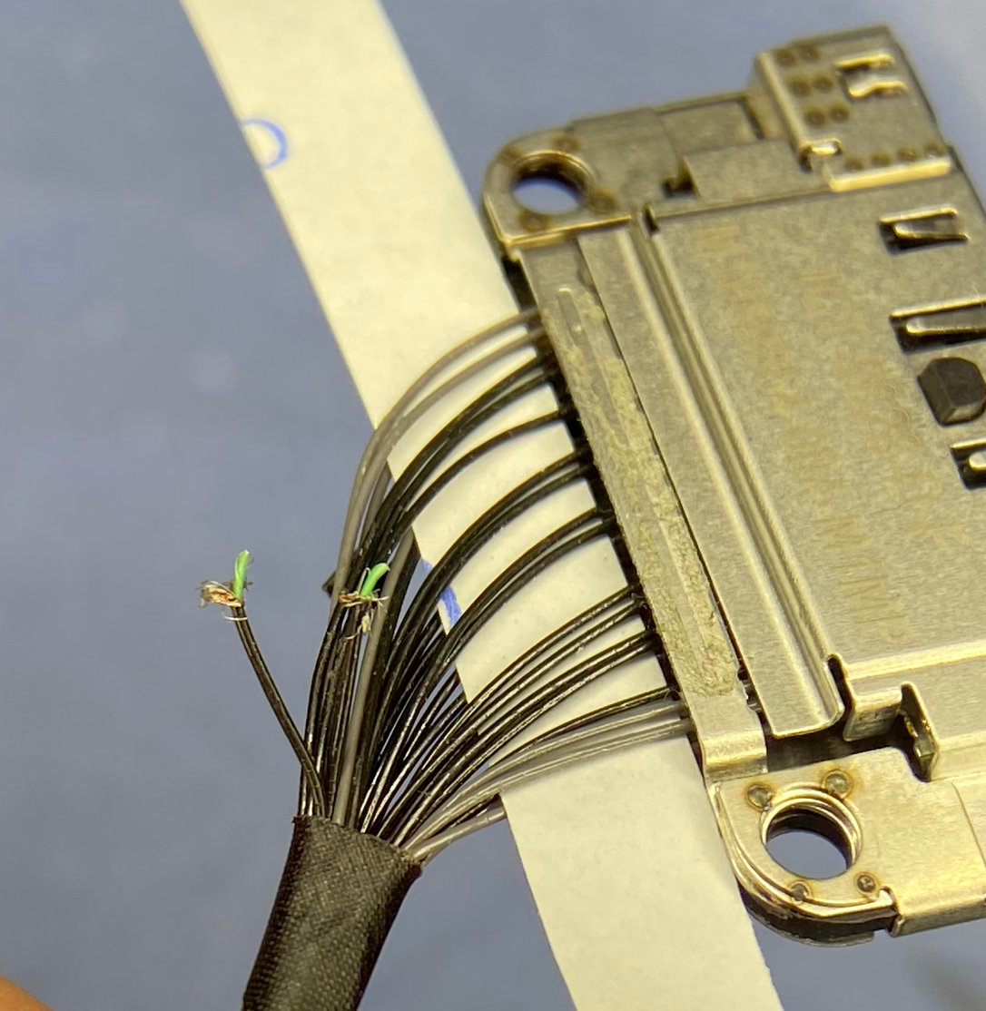
  The connector pinout is known but it is asymmetrical with an exception of the
power input pins. So it's a bit complicated to determine which pins are what.
 </li>
<li>
  As it turns out later on in my exploration: The cabling from the mainboard to
the connector uses micro coax cables which are impossible to solder to as they
are absolutely tiny.
 </li>
</ol>
<p>
<img alt="Micro coax leads" class="left" src="https://dunkelstern.de/articles/2025-01-19/micro_coax.jpg"/>
</p>
<h2 id="changing-gears-lets-steal-the-usb-a-port">
 Changing gears, let's steal the USB-A port
</h2>
<p>
 As I ran into a dead end (ok, a 17 Euro replacement part dead end) with that dock
connector but was determined to make it happen. What am I connecting to the USB-A
port on that laptop anyways? A logitech wireless dongle? An USB stick? Ok sometimes
but we have a USB-C port in addition to the A one.
</p>
<p>
 The USB hub has 4 ports... so if I use one port for Wifi, another one for Bluetooth
I have 2 available. I could add that Logitech dongle, as they are really small,
directly into the laptop and still have one port free.
</p>
<p>
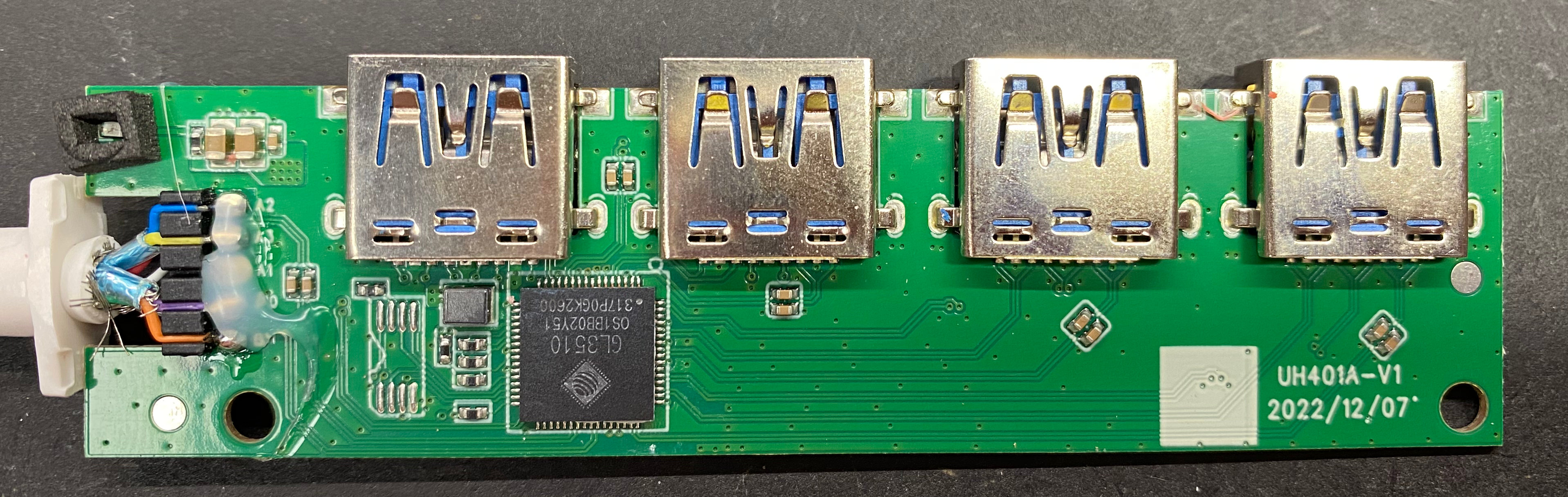
<img alt="USB Hub PCB" class="center" src="https://dunkelstern.de/articles/2025-01-19/usb_hub_pcb.jpg"/>
</p>
<p>
 So how do I get to the USB port contacts? Well...
</p>
<h2 id="dismantling-the-complete-laptop">
 Dismantling the complete laptop
</h2>
<p>
 As I wrote above, I am not sure why Microsoft did go all the way to magnetically
close the laptop. This manifests now in even deeper facepalms.
</p>
<p>
 To get to the screws that hold the mainboard in you have to remove a lot of clip-on
shielding cans (at least they are clipped on not glued). In the process of this
mod I removed the mainboard 3 times, so forgive me as the shields lost a few clips
in that process. That construction is just infuriating as the complete laptop is
made of aluminium so you could probably use that as shielding if done correctly and
just not bother with all the clip-ons.
</p>
<p>
<img alt="Shielding everywhere" class="center" src="https://dunkelstern.de/articles/2025-01-19/clip_on_shields.jpg"/>
</p>
<p>
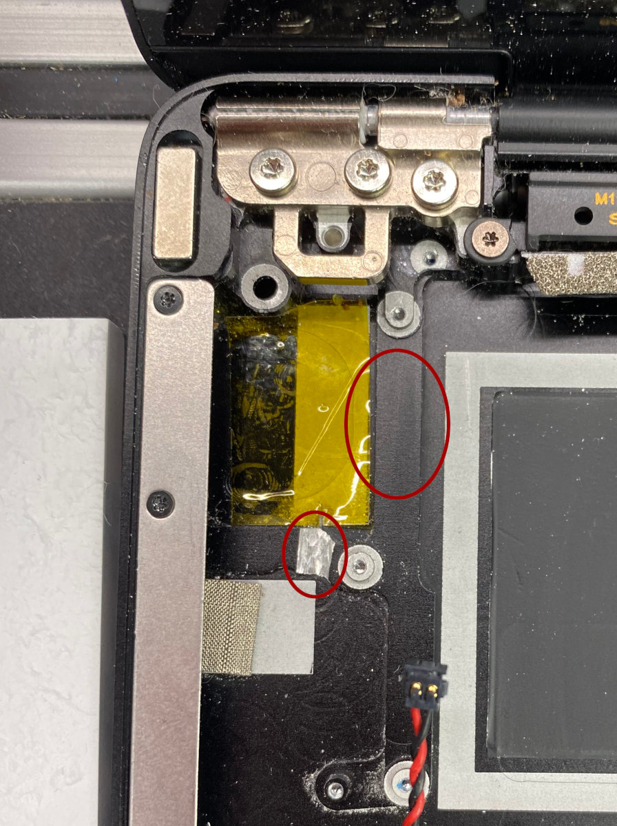
 To be able to route the cables underneath the mainboard I had to modify the case a
bit, some aluminium bridges hat to be filed down a bit to fit the cables in.
</p>
<p>
<img alt="Took the Dremel to the case" class="center" src="https://dunkelstern.de/articles/2025-01-19/dremel_to_case.jpg"/>
</p>
<p>
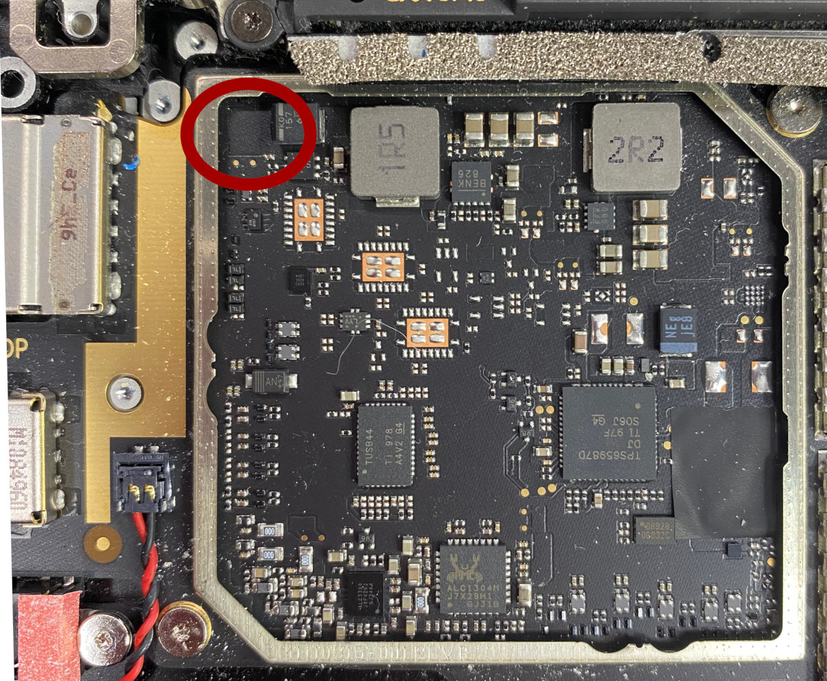
 I could not fit power cables underneath the mainboard so I had to hunt down a source
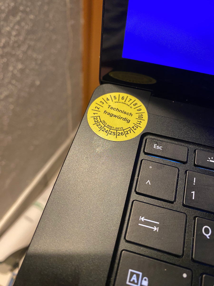
of 5V power from somewhere, turns out the leftmost shield can houses the USB PD
controller as well as battery charging circuit and for unknown reasons to me the
audio circuit. Why would you include the audio stuff in the same shielding can as
the high-power stuff? I don't understand, I would have put them in two seperate
compartments... Yeah well the "technically questionable" sticker on the laptop makes
more and more sense now.
</p>
<p>
<img alt="PD Controller and 5V" class="center" src="https://dunkelstern.de/articles/2025-01-19/pd_controller_5v.jpg"/>
</p>
<h2 id="usb-3-is-something">
 USB 3 is... something
</h2>
<p>
 So the wifi USB stick is a USB 3.0 stick because it can do 1.3 GBit/s theoretically.
It works on USB 2 but then it's just a bit slower. Additionally USB 3 does use less
CPU power than 2 (it seems strange but makes sense) and should be the better protocol
in almost all cases.
</p>
<p>
<img alt="Wifi stick PCB" class="center" src="https://dunkelstern.de/articles/2025-01-19/wifi_pcb.jpg"/>
</p>
<p>
 There's one problem though: It's fricking fast with 5 GBit/s minimum speed, so cabling
has a bit more requirements than USB 2. And this is why I had to rip out the mainboard
three times. The first attempt did not use much shielding, the device wasn't even
detected as "unknown". The second attempt proved very unstable and the third attempt I
was in "yolo"-mode and put everything under a layer of copper tape... Turns out this was
exactly what was needed.
</p>
<p>
 This here was not enough shielding:
</p>
<p>
<img alt="Not enough shielding" class="center" src="https://dunkelstern.de/articles/2025-01-19/not_enough_shielding.jpg"/>
</p>
<h3 id="a-small-detour">
 A small detour
</h3>
<p>
 How does USB even work? The "ancient" specification of the original USB did provide
two speeds: Low speed (1.5 Mbit) and Full speed (12 Mbit). At those speeds you can forgo
most shielding and probably run the signal over wet noodles (now I have to try that).
</p>
<p>
 As the standard is from 1996 you could understand why that is. At that time 12 Mbit was
pretty fast. They did improve over RS232 serial connections by using a pair of twisted
wires for differential signaling (
 <code>
  D-
 </code>
 and
 <code>
  D+
 </code>
 ), the idea is that one wire has the
signal in original form (
 <code>
  D+
 </code>
 ) and the other one has the exact inverted signal. If you
introduce an external interference this will affect both wires at the same time and you
can read the signal by comparing both lines. For example if you get a disturbance that
induces, let's say 3 Volts into both wires, one will have 6.6 Volts and the other one
3 Volts. The difference between both lines will be still 3.6 Volts and you can still
read your data.
</p>
<p>
 In USB 1 and 2 you'll be using 4 lines, Power, the differential data pair and Ground.
You have to make sure to connect
 <code>
  D+
 </code>
 to
 <code>
  D+
 </code>
 on both sides of the cable. USB 1 and 2
differential pairs do not use negative voltages, just zero and "something". USB 1 uses
3.6 Volts, USB 2 much lower 0.45 Volts. The wires are twisted so they will not emit much
EMI and when a disturbance hits them it will hit both wires to the same degree. Cables
are usually shielded with one shield around the complete cable.
</p>
<p>
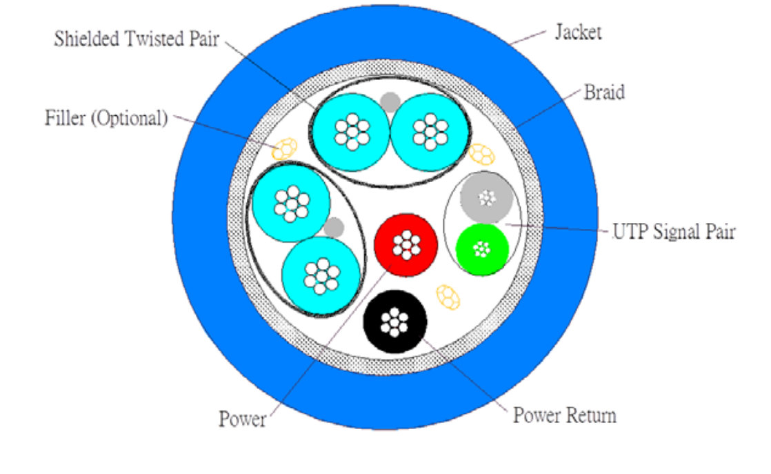
<img alt="USB 3 cable from the spec" class="right" src="https://dunkelstern.de/articles/2025-01-19/usb_cable.jpg"/>
</p>
<p>
 USB 3 is another beast. It uses two differential pairs
 <code>
  RX
 </code>
 and
 <code>
  TX
 </code>
 and as you can see
from the names alone, it does not share one pair for both directions of communication.
It also uses another form of encoding that works much more like PCI express than the
older encoding. This is done because the encoding alone will suppress some of the EMI
of the cable because of it's balancing, but this will go to far for this post.
</p>
<p>
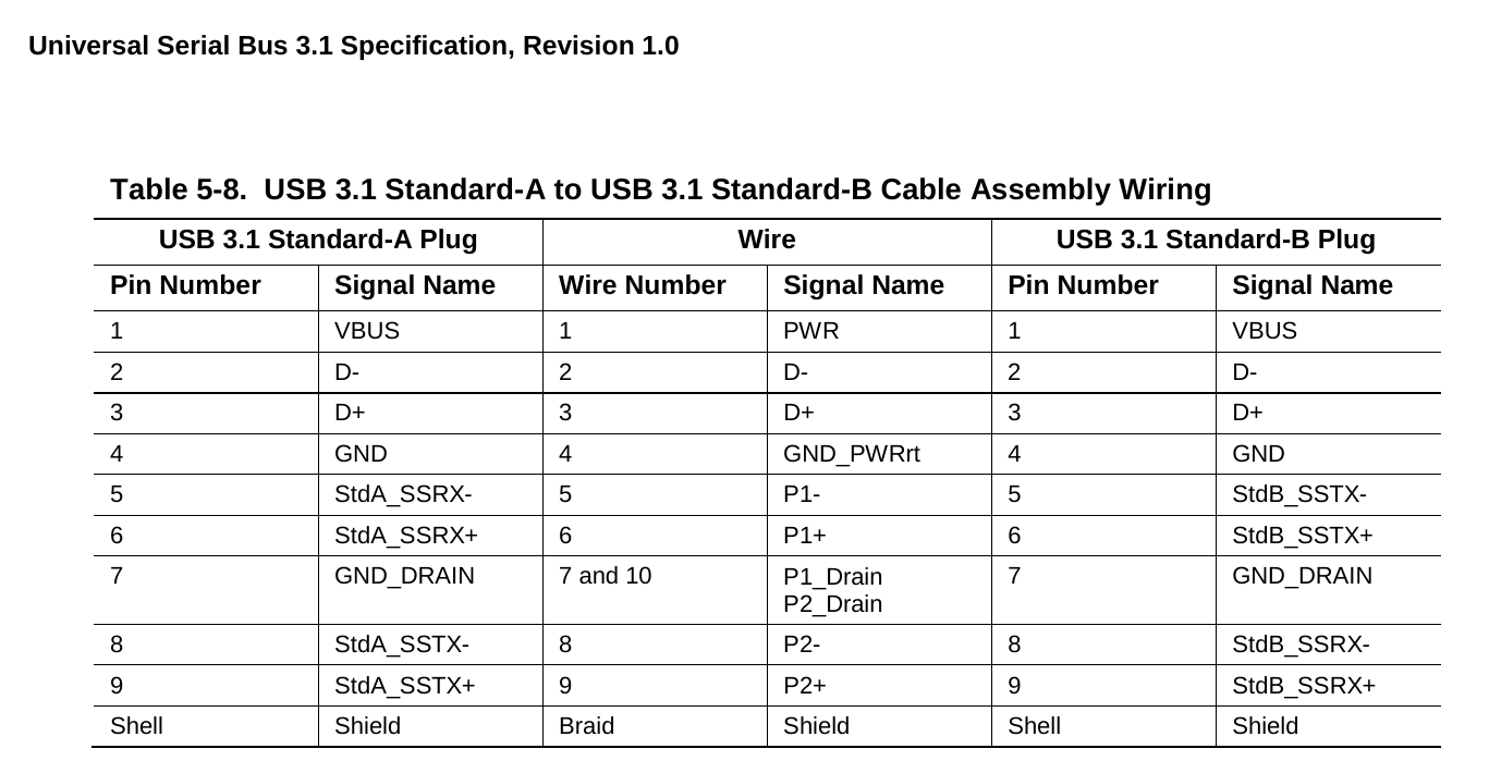
 The interesting thing about USB 3 here is: The cables are cross over cables, so the
 <code>
  RX
 </code>
 line will go to the
 <code>
  TX
 </code>
 terminals and vice versa, but as the link training that
is needed for the receivers on the high speed line interface can detect the polarity
of the
 <code>
  +
 </code>
 and
 <code>
  -
 </code>
 lines you can connect the differential pair in either direction.
Very nice... would be cool if I knew that before doing this project...
</p>
<p>
<img alt="USB 3 connector definition from the spec" class="center" src="https://dunkelstern.de/articles/2025-01-19/usb3_cable_crossover.png"/>
</p>
<p>
 As we're still talking about a digital interface and we're trying to transmit and
receive 5 Gbit/s the requirements for shielding go through the roof. Both differential
pairs have to be twisted and shielded from each other as well as the world. As we
need a very stable ground path at those speeds there is a drain wire embedded with
the twisted pair that acts as a signal ground return. It is not clear to me from
the specs if that wire may or may not be connected to the same ground as the shielding.
But as I looked into the USB hub... they did just that.
</p>
<p>
<img alt="USB hub no drain" class="right" src="https://dunkelstern.de/articles/2025-01-19/usb_hub_no_drain.jpg"/>
</p>
<p>
 Oh by the way: USB 2 and USB 3 do not share any data lines, a USB 3 port is basically
a USB 2 port and a USB 3 port in one connector, the old
 <code>
  D+
 </code>
 and
 <code>
  D-
 </code>
 are completely
seperate and even use different host controllers, so if you have two devices, one USB 3
and one USB 1/2 you could basically split a port without even using a hub.
</p>
<h3 id="back-on-topic">
 Back on topic
</h3>
<p>
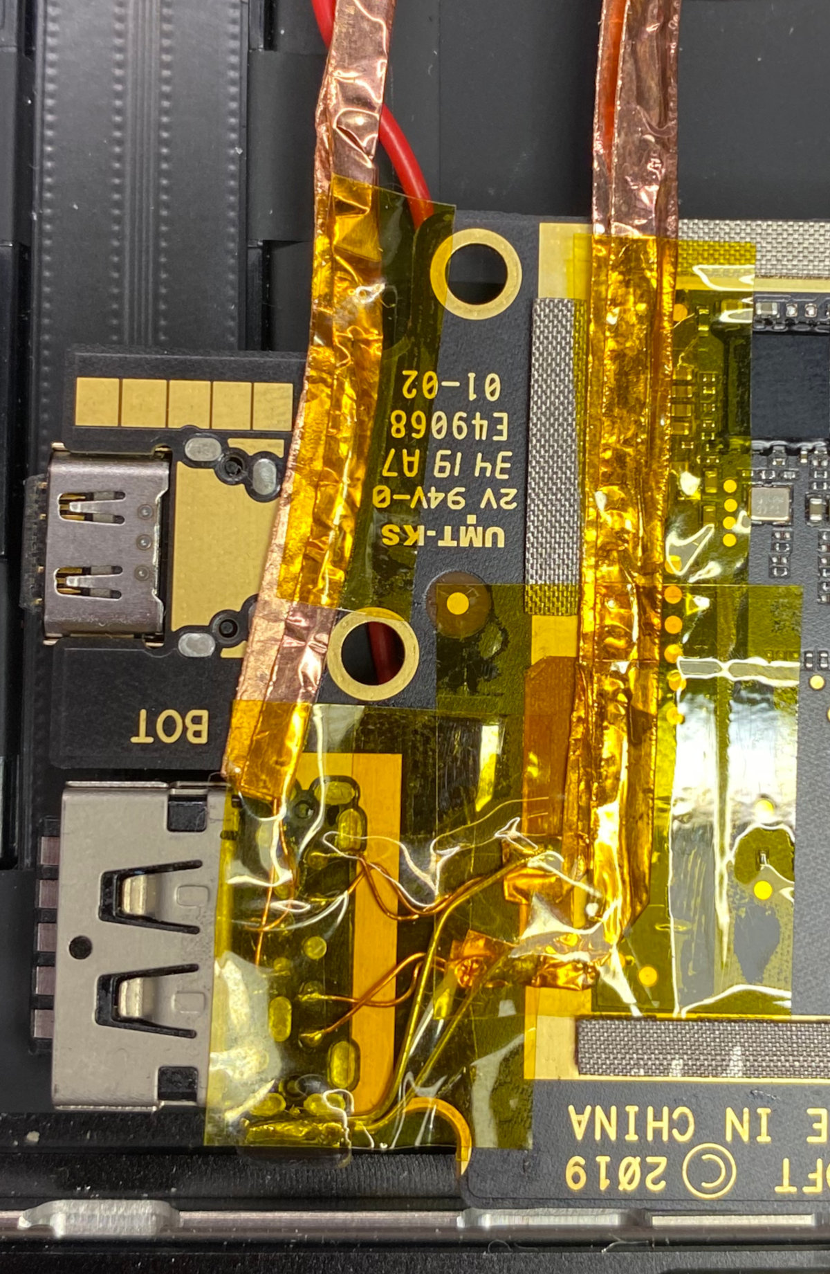
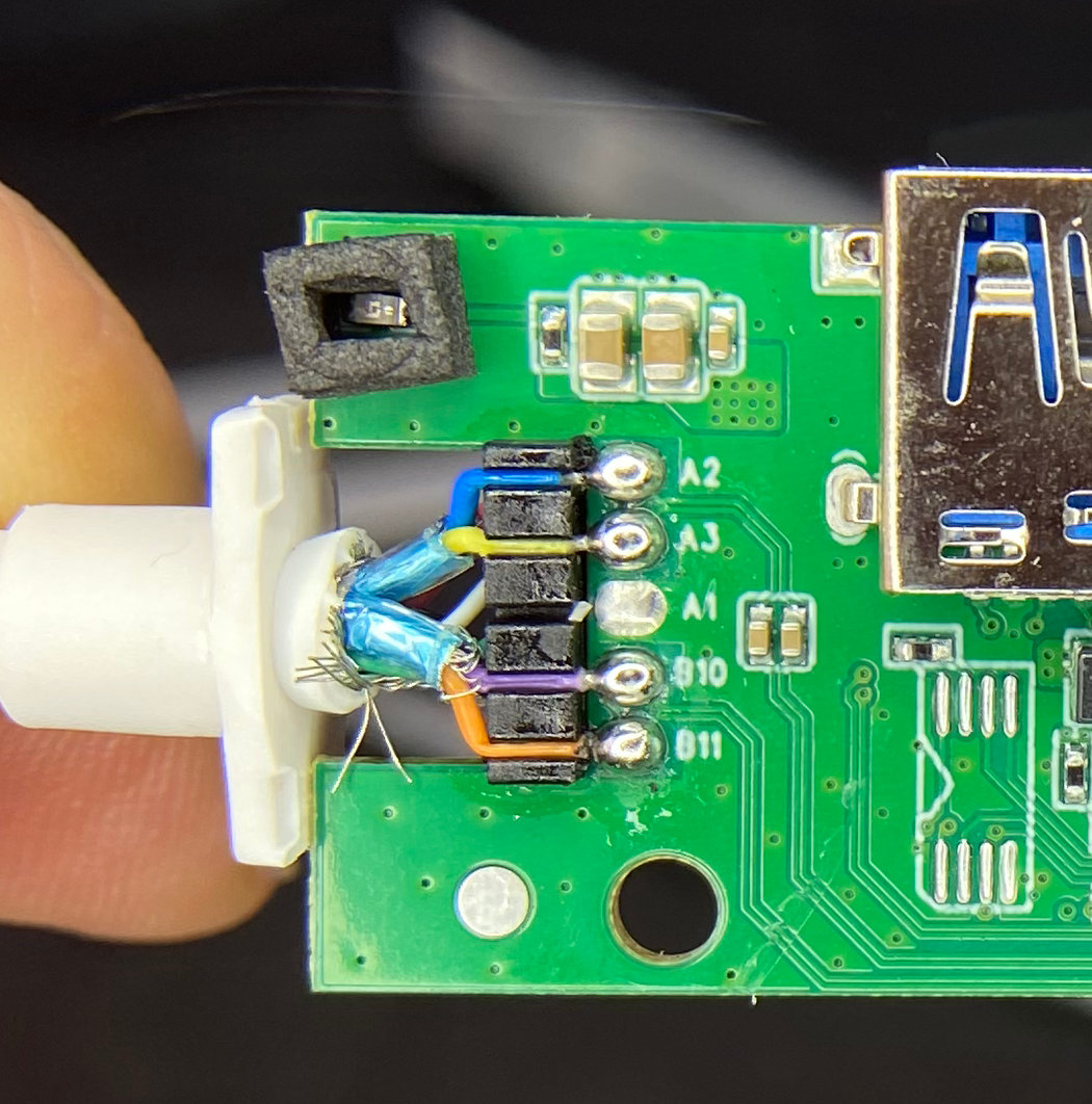
 You can see I stole the data lines from the USB-A port, re-inserted the mainboard
and connected that to the PCB of the USB hub.
</p>
<p>
<img alt="All cables routed" class="center" src="https://dunkelstern.de/articles/2025-01-19/all_routed.jpg"/>
</p>
<p>
 If you're wondering: Yes I absolutely took a Dremel to the PCB of the hub and
antenna of the wifi stick and cut stuff off. There was nothing on there, it was
just "structural".
</p>
<p>
 After hardwiring everything in with enamel wire (also known as transformator
wire. It's basically copper wire with some kind of coating on there to avoid short
circuits) and using copious amounts of copper tape to shield everything with a lot
of swearing and probably rebooting the laptop about 100 times it finally worked.
</p>
<p>
 After that it was just a lot of puzzling to get everything in there.
</p>
<h2 id="finishing-words">
 Finishing words
</h2>
<p>
<img alt="Wifi connection screenshot" class="right" src="https://dunkelstern.de/articles/2025-01-19/wifi_connected.png"/>
</p>
<p>
 It's interesting on what you can do that
 <em>
  should
 </em>
 be impossible if you ask someone
who designs PCBs for a living. Probably I am just lucky that it works, probably
the hardware can take more "abuse" than most people think, but probably it's just
good enough. It would be interesting to actually measure the insertion losses and
impedances of those hacked wires but I don't have the equipment, nor the knowledge
to do that.
</p>
<p>
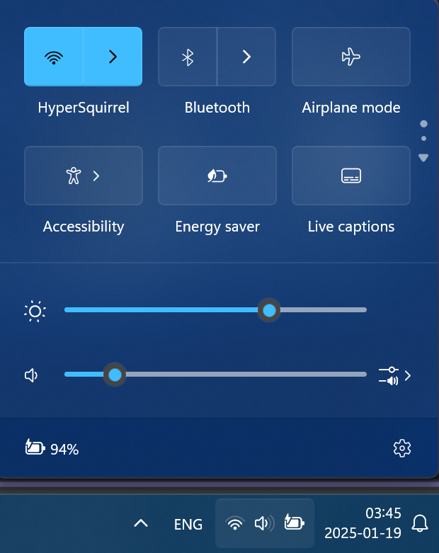
 So does it work then? Yes, yes it absolutely does. I am even a bit impressed how
good the Wifi signal is in that aluminium box of the laptop. It seems the keyboard
is "leaky" enough to let the wifi signal through.
</p>
<p>
<img alt="Technically questionable" class="center" src="https://dunkelstern.de/articles/2025-01-19/technically_questionable.jpg"/>
</p>
 ]]></content>
  <author>
    <email>hallo@dunkelstern.de</email>
    <name>Johannes Schriewer</name>
  </author>
 </entry>
 
 <entry>
  <title>Ducky One 3 conversion to QMK</title>

  <link rel="alternate" type="text/html" href="https://dunkelstern.de/articles/2024-03-09/index.html"/>
  <id>urn:uuid:7da37844-a2df-5e85-98c8-457ffcafddbf</id>
  <published>2024-03-09T00:00:00+01:00</published>
  <updated>2024-03-13T19:25:08+01:00</updated>
  <summary><![CDATA[ <p>
 My partner
 <a href="https://corteximplant.com/@chaotin">
  @chaotin@corteximplant.com
 </a>
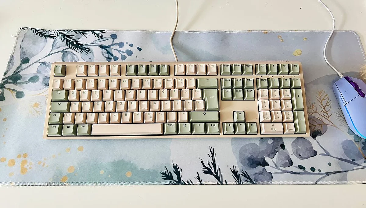
 was gifted a Ducky One 3 Matcha
mechanical keyboard. I converted that thing to a Raspberry Pi Pico (RP2040) chip with QMK firmware.
</p>
 ]]></summary>
  <content type="html"><![CDATA[ <h2 id="what">
 What
</h2>
<p>
<img alt="PCB" class="center" src="https://dunkelstern.de/articles/2024-03-09/keyboard.webp"/>
</p>
<p>
 My partner
 <a href="https://corteximplant.com/@chaotin">
  @chaotin@corteximplant.com
 </a>
 was gifted a Ducky One 3 Matcha
mechanical keyboard. I converted that thing to a Raspberry Pi Pico (RP2040) chip with QMK firmware.
</p>
<h2 id="why">
 Why
</h2>
<p>
 The firmware of the Ducky keyboard did not compensate for bouncing keys correctly and it seems Ducky abandoned
updating the firmware for that device. So the keyboard was basically unusable because all the time key-presses
repeated multiple times.
</p>
<p>
 Try to write any length of text with an unreliable keyboard.
</p>
<p>
 There are basically 3 approaches to fixing this:
</p>
<ol>
<li>
  Reverse engineer the Ducky firmware and firmware update process. This has been done by
  <code>
   usedbytes
  </code>
  on github:
  <a href="https://github.com/usedbytes/ducky-tools">
   Ducky-Tools on Github
  </a>
  for another hardware platform from Ducky, but
it would not work for the platform on which the One 3 is based on. Furthermore I would have to reverse engineer
the original firmware to find the debouncing code and binary patch that.
 </li>
<li>
  Write a new keyboard firmware for the Nuvoton chip that is on the board. This would mean to reverse engineer the
PCB first and then learn how to write software for that chip and how to get it onto the internal Flash. It seems
there is actually a programming header on the PCB, so at least flashing would be not the biggest problem.
 </li>
<li>
  Remove the Nuvoton chip, reverse engineer the PCB enough to find out how to access the keyboard matrix and hot-
wire a Raspberry Pi Pico in there. This seemed the most straight forward thing to do, so I started by reverse
engineering the PCB.
 </li>
</ol>
<h2 id="how">
 How
</h2>
<h3 id="reverse-engineering">
 Reverse engineering
</h3>
<p>
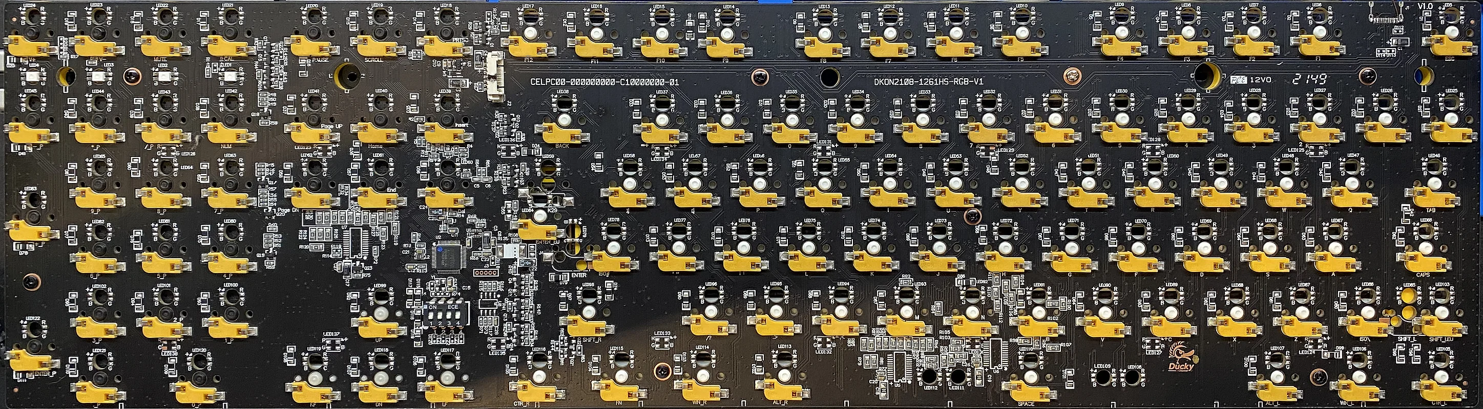
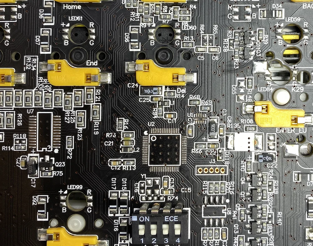
<img alt="PCB" class="center" src="https://dunkelstern.de/articles/2024-03-09/full_pcb.webp"/>
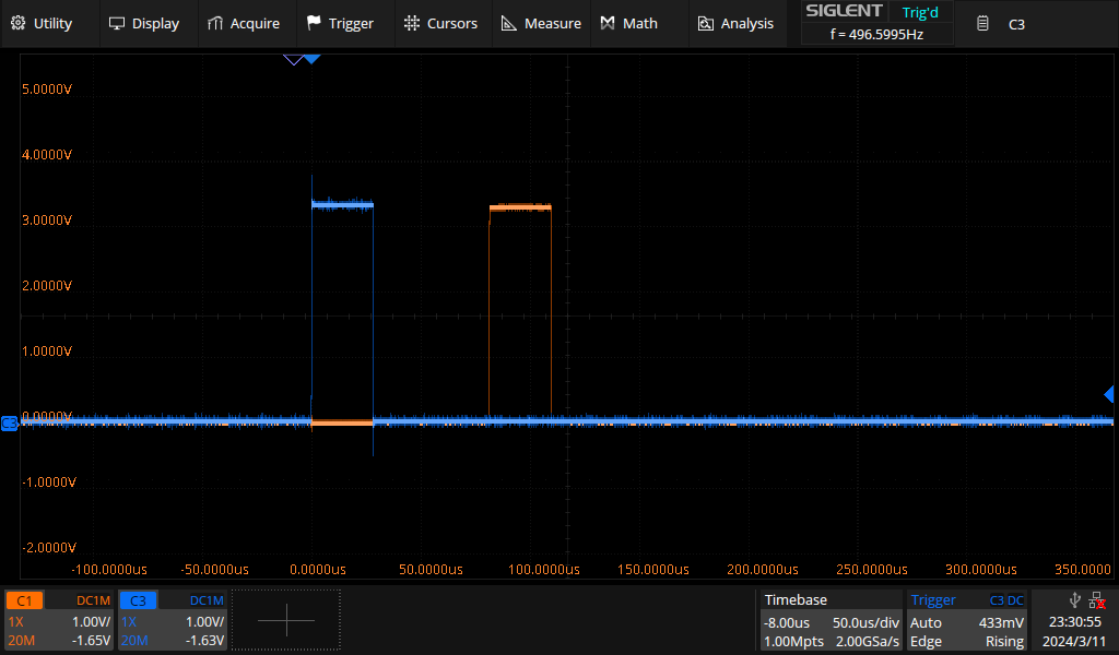
<img alt="Oscilloscope trace" class="right" src="https://dunkelstern.de/articles/2024-03-09/oscilloscope_trace.png"/>
</p>
<p>
 If you have a working keyboard the first thing to try is powering it up and probing around with an oscilloscope
to find out where the rows of the keyboard matrix are accessible. You should see a rectangle pulse on each row
at around 250 to 1000 Hz. For each row the pulse should be shifted by one pulse length. To find out the row order
use two channels of your oscilloscope, trigger on one and look at both channels to see where the pulses are in
relation to each other.
</p>
<p>
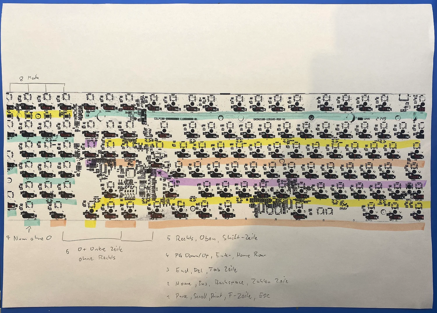
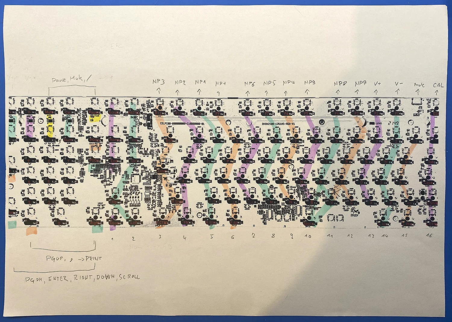
<img alt="Rows marked on a scan" class="left" src="https://dunkelstern.de/articles/2024-03-09/rows_paper.webp"/>
</p>
<p>
 On the One 3 I could find that pulse on each of the switch contacts on the right side and the original firmware
scanned with 500 Hz. I found there to be 8 rows with distinct pulses on them, starting with the top row
(ESC, F-Keys), then going down the keyboard rows as expected and finished by the Num-pad. The last row were just
the four media keys above the Num-pad (Calculator, Mute, Vol down, Vol up).
</p>
<p>
<img alt="Columns marked on a scan" class="right" src="https://dunkelstern.de/articles/2024-03-09/cols_paper.webp"/>
</p>
<p>
 The next step was to find the colums that are connected together, I had to find that by probing with a multimeter
in continuity mode. My partner was really annoyed after hearing me search for connections with the beeping
mulimeter for about an hour...
</p>
<p>
 Usually the keyboards have one diode per key to avoid triggering "wrong keys" if too many keys are pressed at
the same time (N-Key rollover). Gladly the One 3 has them near the key switches and I could measure from diode
anode (the pad without the line) to other diode anodes.
</p>
<h3 id="bricking-the-keyboard-for-real">
 Bricking the keyboard for real
</h3>
<p>
 After finding out what is what i decided to yolo it and remove the Nuvoton chip with hot air:
</p>
<p>
<img alt="Nuvoton chip removed" class="center" src="https://dunkelstern.de/articles/2024-03-09/chip_removed.webp"/>
</p>
<p>
 Now the keyboard was dead and I had to come up with a plan to hot-wire a RP2040 into that thing. The first thing
I did was to check where to put it. The One 3 has much space in the keyboard case, so this was not a big problem
at all.
</p>
<p>
<img alt="Raspi Pico stuck to the PCB" class="left" src="https://dunkelstern.de/articles/2024-03-09/pico.webp"/>
</p>
<p>
 Before mounting the RP2040 permanently with VHB tape I had to remove the Micro USB Port (clearance!) and the LED
from the prototyping module. I needed the pin that has the LED connected (
 <code>
  GPIO25
 </code>
 ) for one of the indicator LEDs
of the keyboard. Alternatively I could have skipped the multimedia keys or not indicate Scroll-Lock
(who uses Scroll-Lock?), but the perfectionist in me wanted to have a fully functioning keyboard, so the LED
had to go.
</p>
<p>
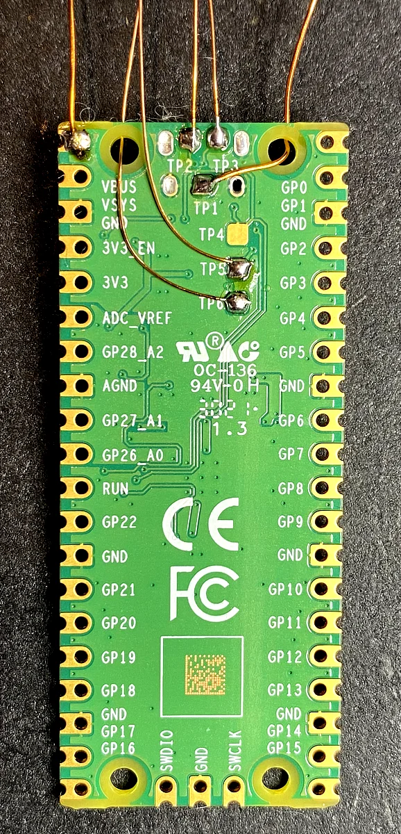
<img alt="Test pads on the back of the Pico" class="right" src="https://dunkelstern.de/articles/2024-03-09/testpads.webp"/>
</p>
<p>
 The other test points on the Pico board are connected to GND and USB (thanks for that Raspberry Pi Foundation).
This means we can wire the Pico into the original USB port of the keyboard without trying to micro-solder onto
the pads of the Micro-USB port (I mean this would not be the smallest connection I've ever made but thanks, no
thanks...). As we only running a keyboard in low speed mode I did not bother to make the D+ and D- wires the
exact same length or something like that. It will just work fine.
</p>
<p>
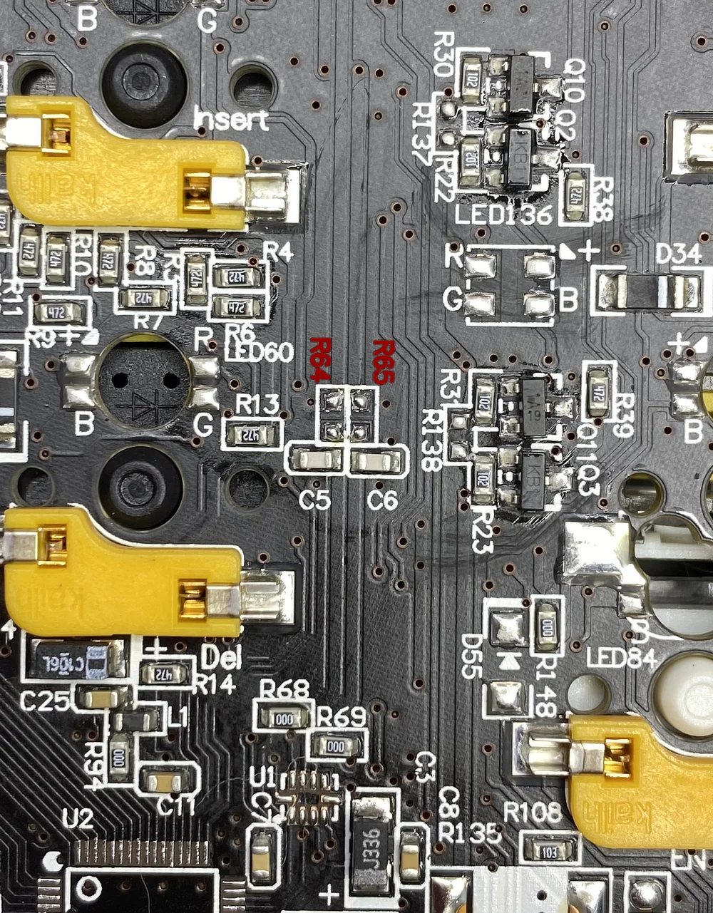
<img alt="Accessing the USB traces on the PCB" class="left" src="https://dunkelstern.de/articles/2024-03-09/usb_resistor.webp"/>
</p>
<p>
 To gain access to the USB-Port of the keyboard I traced where the original chip was connected and found a lot
of stuff in the path (resistors, ferrite beads, etc.). We do not need all that stuff for the Pico, so I removed
the first item in that path which were some 0604 resistors (
 <code>
  R64
 </code>
 is D- and
 <code>
  R65
 </code>
 is D+) and connected the Pico
with enamel wire to those pads. GND did come from the programming header (
 <code>
  J3
 </code>
 pin 1) and USB bus power was
found at a resettable fuse which was not populated on my board (left pad of
 <code>
  R135
 </code>
 ).
</p>
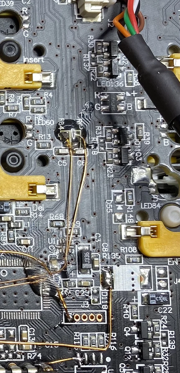
<p>
<img alt="USB connected" class="center" src="https://dunkelstern.de/articles/2024-03-09/usb_connected.webp"/>
</p>
<p>
 Now I could try to program the Pico via the original USB-Port... it worked first time!
</p>
<h3 id="mvp">
 MVP
</h3>
<p>
 Next up: do the minimum viable thing, blink the Num-Lock LED.
</p>
<p>
 For this I tried to reverse engineer the cascade of transistors and mosfets on the PCB and I think they
multiplex all the LEDs together with the row pulses, because there are some spots on the PCB where you
could solder on LED drivers and full RGB backlighting in addition to the indicator LEDs. I could not make
heads or tails of it and tried to find a suitable path.
</p>
<p>
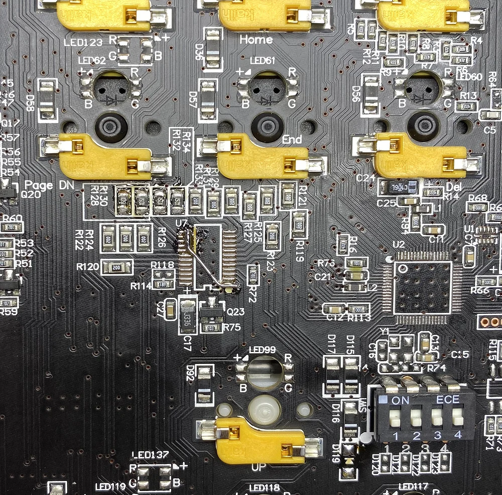
<img alt="Driver Pins shorted" class="right" src="https://dunkelstern.de/articles/2024-03-09/driver_pins.webp"/>
</p>
<p>
 To get GND to the LEDs i shorted some pins of one of the not installed LED drivers and replaced some
0805 resistors to be our current limiters. The original resistors in those spots were about 20 Ohms, so
I think they overdrove the LEDs by a big margin to compensate for the matrix multiplexing. This is usually
not a problem. LEDs release the magic smoke because they get too hot inside, if you can guarantee a 1ms
pulse all 20ms for example you could probably overdrive the LED by a factor of 10 and be on the safe side
still because it has time to dissipate the heat between the pulses. We're not doing that so I had to replace
those resistors (
 <code>
  R128
 </code>
 to
 <code>
  R131
 </code>
 ) with something more reasonable. As my partner complained already about the
searing brightness of those LEDs I went with the conservative selection of 1.5 kOhms.
</p>
<p>
 I then connected the
 <code>
  TP5
 </code>
 from the Pico to the positive terminal of the Num-Lock LED and flashed a simple
blink sketch and it worked. Good.
</p>
<h3 id="unbricking-in-the-case-of-failure">
 Unbricking in the case of failure
</h3>
<p>
 If you somehow brick the firmware on a Pico you can always go back to firmware update mode by holding the
 <code>
  BOOTSEL
 </code>
 key on the protoboard. The board will be inside the keyboard in the forseeable future, but I wanted
to have that option, should anything go wrong in the future, while not having to unscrew the case and push a
button once. The One 3 has a DIP switch on the bottom to switch between Mac and Windows modes and deactivate
the Windows key, etc. This DIP switch is the ideal candidate for that boot mode selection button. Let's modify
it a bit.
</p>
<p>
 At first I removed the diode that probably integrated the DIP switch into the keyboard matrix (why? I don't
know...), thats
 <code>
  D119
 </code>
 for those following along at home...
</p>
<p>
 I probed the path of the DIP switch and found out that the top 4 pins are shorted together, so I shorted that
to GND in addition (
 <code>
  U8
 </code>
 pin 4 is a good location for GND) and connected
 <code>
  TP6
 </code>
 to the top pad of the removed
diode. Now we can switch to firmware update mode by flicking the 4th DIP switch up and re-connecting the
keyboard. Turn the switch off again to boot in keyboard mode.
</p>
<h3 id="the-copper-spider-enters-the-scene">
 The copper spider enters the scene
</h3>
<p>
 As we have all bottom pads of the Pico connected where they belong we can stick it to the board with VHB
tape or a dab of hot glue.
</p>
<p>
 For the matrix connections I just used thin enamel wire again. I have a big roll of that and it makes connecting
to small SMD pads relatively easy. Some wire is coated in an enamel that just burns of if you touch it with a
soldering iron, this would be ideal as you could add the connections very fast in that way. No such luck with
my wire. I mean it burns off the coating if you wait long enough, but at that time the PCB would be damaged
for sure. So I removed a bit of the coating by first scraping it with a scalpel and then burning the remainder
off with the iron on both ends of the measured wire.
</p>
<p>
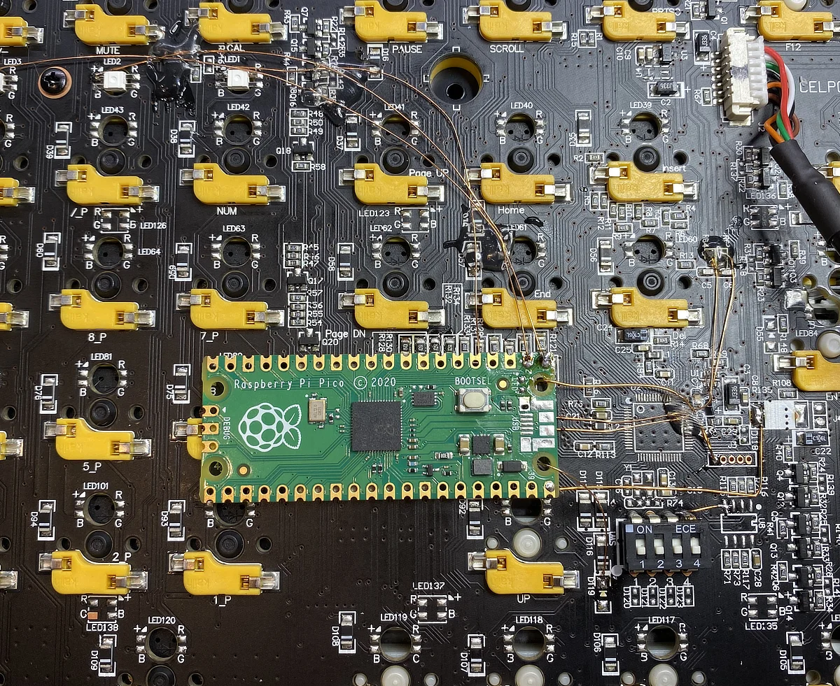
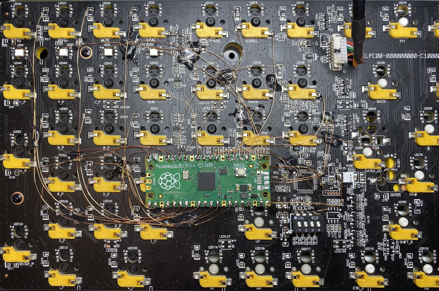
<img alt="Finished wiring" class="right" src="https://dunkelstern.de/articles/2024-03-09/everything_connected.webp"/>
</p>
<p>
 I wired the matrix in this way:
</p>
<p>
 For the rows you have to use the right terminal of any of the listed key switches.
</p>
<table>
<thead>
<tr>
<th>
    Row
   </th>
<th>
    GPIO
   </th>
<th>
    Switch
   </th>
</tr>
</thead>
<tbody>
<tr>
<td>
    0
   </td>
<td>
    GP2
   </td>
<td>
    Scroll Lock
   </td>
</tr>
<tr>
<td>
    1
   </td>
<td>
    GP3
   </td>
<td>
    Insert
   </td>
</tr>
<tr>
<td>
    2
   </td>
<td>
    GP4
   </td>
<td>
    Delete
   </td>
</tr>
<tr>
<td>
    3
   </td>
<td>
    GP5
   </td>
<td>
    Enter
   </td>
</tr>
<tr>
<td>
    4
   </td>
<td>
    GP6
   </td>
<td>
    Up
   </td>
</tr>
<tr>
<td>
    5
   </td>
<td>
    GP7
   </td>
<td>
    Left
   </td>
</tr>
<tr>
<td>
    6
   </td>
<td>
    GP8
   </td>
<td>
    Num Lock
   </td>
</tr>
<tr>
<td>
    7
   </td>
<td>
    GP9
   </td>
<td>
    Calculator
   </td>
</tr>
</tbody>
</table>
<p>
 For the columns always go with the top pad of the diode (the one without the line)
for the switch in the list.
</p>
<table>
<thead>
<tr>
<th>
    Column
   </th>
<th>
    GPIO
   </th>
<th>
    Switch
   </th>
</tr>
</thead>
<tbody>
<tr>
<td>
    0
   </td>
<td>
    GP10
   </td>
<td>
    Scroll Lock
   </td>
</tr>
<tr>
<td>
    1
   </td>
<td>
    GP11
   </td>
<td>
    Insert
   </td>
</tr>
<tr>
<td>
    2
   </td>
<td>
    GP12
   </td>
<td>
    Numpad 3
   </td>
</tr>
<tr>
<td>
    3
   </td>
<td>
    GP13
   </td>
<td>
    Numpad 2
   </td>
</tr>
<tr>
<td>
    4
   </td>
<td>
    GP14
   </td>
<td>
    Numpad 1
   </td>
</tr>
<tr>
<td>
    5
   </td>
<td>
    GP15
   </td>
<td>
    Numpad Plus
   </td>
</tr>
<tr>
<td>
    6
   </td>
<td>
    GP16
   </td>
<td>
    Numpad 6
   </td>
</tr>
<tr>
<td>
    7
   </td>
<td>
    GP17
   </td>
<td>
    Numpad 5
   </td>
</tr>
<tr>
<td>
    8
   </td>
<td>
    GP18
   </td>
<td>
    Numpad 4
   </td>
</tr>
<tr>
<td>
    9
   </td>
<td>
    GP19
   </td>
<td>
    Numpad 9
   </td>
</tr>
<tr>
<td>
    10
   </td>
<td>
    GP20
   </td>
<td>
    Numpad 8
   </td>
</tr>
<tr>
<td>
    11
   </td>
<td>
    GP21
   </td>
<td>
    Numpad 7
   </td>
</tr>
<tr>
<td>
    12
   </td>
<td>
    GP22
   </td>
<td>
    Volume Up
   </td>
</tr>
<tr>
<td>
    13
   </td>
<td>
    GP26
   </td>
<td>
    Volume Down
   </td>
</tr>
<tr>
<td>
    14
   </td>
<td>
    GP27
   </td>
<td>
    Mute
   </td>
</tr>
<tr>
<td>
    15
   </td>
<td>
    GP28
   </td>
<td>
    Calculator
   </td>
</tr>
</tbody>
</table>
<p>
 As you can see it is a good thing that the Numpad is connected as one row below the alpha numeric block.
We can avoid running enamel wire over the whole keyboard this way and are safely contained below the
Num-pad and arrow key areas.
</p>
<h3 id="finishing-touches">
 Finishing touches
</h3>
<p>
 To finish the electronics side of the build we have to connect the Caps Lock and Scroll Lock LEDs.
I have mapped them to
 <code>
  GPIO0
 </code>
 and
 <code>
  GPIO1
 </code>
 respectively. Just run a wire to the positive terminal of
the leds and we're ready here.
</p>
<p>
 I added some globs of hotmelt glue to secure the fine wires and placed the keyboard in it's lower
case at this moment and got to configuring QMK.
</p>
<h3 id="qmk">
 QMK
</h3>
<p>
 For compiling QMK I would refer to
 <a href="https://docs.qmk.fm/#/newbs_getting_started">
  the tutorial
 </a>
 . If
you want to pull my keyboard configuration you may do so at my
 <a href="https://github.com/dunkelstern/qmk_firmware/tree/ducky_one_3">
  QMK fork at my Github
 </a>
 . If you're
using my fork, make sure to check out the
 <code>
  ducky_one_3
 </code>
 branch.
</p>
<p>
 Compile the firmware with the
 <code>
  qmk
 </code>
 cli by running:
</p>
<pre><code>qmk compile --keyboard dunkelstern/ducky_one_3_rp2040 --keymap default
qmk flash
</code></pre>
<p>
 and then connect the keyboard with the DIP switch position 4 turned on and mount the drive that appears.
</p>
 ]]></content>
  <author>
    <email>hallo@dunkelstern.de</email>
    <name>Johannes Schriewer</name>
  </author>
 </entry>
 
 <entry>
  <title>LittleSpeaker</title>

  <link rel="alternate" type="text/html" href="https://dunkelstern.de/articles/2024-01-13/index.html"/>
  <id>urn:uuid:9510ad2a-9853-533b-9132-1fba5493705d</id>
  <published>2024-01-13T00:00:00+01:00</published>
  <updated>2024-03-12T19:52:45+01:00</updated>
  <summary><![CDATA[ <p>
 The idea is to build a small mono speaker that is repairable, hackable and can do
some more advanced things than just being a Bluetooth speaker.
</p>
 ]]></summary>
  <content type="html"><![CDATA[ <h2 id="what-is-littlespeaker">
 What is LittleSpeaker
</h2>
<p>
 The idea is to build a small mono speaker that is repairable, hackable and can do
some more advanced things than just being a Bluetooth speaker.
</p>
<p>
 Design of the enclosure is by Jennifer Leis, Firmware and electronics by me.
</p>
<p>
<img alt="Assembly graphic" class="center nopixel" src="https://dunkelstern.de/articles/2024-01-13/assembly.png"/>
</p>
<p>
 You can find all design files and the firmware in the
 <a href="https://github.com/dunkelstern/LittleSpeaker">
  LittleSpeaker Github Repository
 </a>
</p>
<p>
 This blog entry is basically a modified Readme from that repository.
</p>
<h2 id="enclosure">
 Enclosure
</h2>
<p>
 The prototype enclosure was 3D printed and is held together by a hinge and just one
M3 screw.
</p>
<p>
 You will need:
</p>
<ol>
<li>
  1x Front bezel
  <div>
<img alt="Front bezel graphic" class="center nopixel" src="https://dunkelstern.de/articles/2024-01-13/front-bezel.png"/>
</div>
</li>
<li>
  1x Back bezel
  <div>
<img alt="Back bezel graphic" class="center nopixel" src="https://dunkelstern.de/articles/2024-01-13/back-bezel.png"/>
</div>
</li>
<li>
  1x Back plate
  <div>
<img alt="Back plate graphic" class="center nopixel" src="https://dunkelstern.de/articles/2024-01-13/back-plate.png"/>
</div>
</li>
<li>
  1x Front plate
  <div>
<img alt="Front plate graphic" class="center nopixel" src="https://dunkelstern.de/articles/2024-01-13/front-plate.png"/>
</div>
</li>
<li>
  1x Hinge
  <div>
<img alt="Hinge graphic" class="center nopixel" src="https://dunkelstern.de/articles/2024-01-13/hinge.png"/>
</div>
</li>
<li>
  2x Knob
  <div>
<img alt="Knob graphic" class="center nopixel" src="https://dunkelstern.de/articles/2024-01-13/knob.png"/>
</div>
</li>
<li>
  Two small pieces of wood or plastic as holding braces for the PCBs
that will be accessible from the outside (15 x 40mm two M3 trough holes)
  <div>
<img alt="Braces graphic" class="center nopixel" src="https://dunkelstern.de/articles/2024-01-13/brace.png"/>
</div>
</li>
<li>
  Brass hotmelt inserts for screwing the front and back together and for the braces:
  <ul>
<li>
    1 x M3x6
   </li>
<li>
    4 x M3x4
    <div>
<img alt="Brass insert graphic" class="center nopixel" src="https://dunkelstern.de/articles/2024-01-13/brass-insert.png"/>
</div>
</li>
</ul>
</li>
<li>
  5x M3x10 Cap head screws
 </li>
<li>
  Some self-tapping screws to attach the power switch.
 </li>
<li>
  A piece of Copper wire to fit into the hinge to connect the front and back pieces
 </li>
<li>
  Glue to glue the front and back plates into the bezels and some foam rubber strips
or foam tape for securing stuff
 </li>
<li>
  Some wool or cotton to fill the empty spaces so no wires rattle around.
 </li>
</ol>
<p>
 When printing the front plate make sure to change the settings for the speaker grille
part to not print any bottom or top layers, use hexagon/honeycomb infill and use about 
40% infill strength. You can remove the speaker grille part if you want to have the
speaker open like you can see in the rendered graphic of the assembly.
</p>
<h3 id="after-printing">
 After printing
</h3>
<ol>
<li>
  Remove the supports from the holding brackets of the speaker driver.
There should be thin walled supports that have been designed into the part.
 </li>
<li>
  Melt the inserts into the brace holes and the front plate.
 </li>
<li>
  Glue the front and backplates into their bezels
 </li>
<li>
  Find a piece of copper wire that fits into the holes in the hinge.
The front and back bezels both have a small hole through which you can insert
the wire through the hinge part. If assembled and the hinge is freely rotating
you can use a small screw driver to bend the wire in the hole to avoid it falling out.
Alternatively insert a dab of glue to close the hole.
 </li>
<li>
  The SD card slot and USB-C port probably need some cleanup and filing to fit perfectly.
 </li>
</ol>
<h2 id="electronics">
 Electronics
</h2>
<p>
 The electronics in this devices are meant to be modular, so developer boards for all
components were used and the wiring connections mostly have dupont connectors to be able
to remove/replace a component without de-soldering anything. You can of course skip the
connectors and solder everything together, that's your choice.
</p>
<h3 id="bom">
 BOM
</h3>
<ul>
<li>
  DFRobot Firebeetle 2 ESP32-E (ESP32 development board with battery charger and USB-C)
  <div>
<img alt="Firebeetle ESP32-E" class="center" src="https://dunkelstern.de/articles/2024-01-13/esp32-firebeetle-esp32-e.jpg"/>
</div>
</li>
<li>
  I2S DAC usually something like a
  <code>
   PCM5102A
  </code>
<div>
<img alt="I2S DAC" class="center" src="https://dunkelstern.de/articles/2024-01-13/i2s-dac-PCM5102A.jpg"/>
</div>
</li>
<li>
  Micro SD Card reader, see below for more instructions!
  <div>
<img alt="SD-Card Reader" class="center" src="https://dunkelstern.de/articles/2024-01-13/micro-sd-card-reader.jpg"/>
</div>
</li>
<li>
  Class D Amplifier for 1.5W to 4W with volume regulation, for example
  <code>
   PAM8403
  </code>
<div>
<img alt="Class D amp" class="center" src="https://dunkelstern.de/articles/2024-01-13/amp-PAM8403.jpg"/>
</div>
</li>
<li>
  "57mm Speaker" (yes this is the search term). You can probably use any speaker you
want as long as it is 4-8 Ohms and can work with your amplifier.
  <div>
<img alt="Speaker" class="center" src="https://dunkelstern.de/articles/2024-01-13/speaker-57mm.jpg"/>
</div>
</li>
<li>
  LiIon 18650 Battery
  <div>
<img alt="18650" class="center" src="https://dunkelstern.de/articles/2024-01-13/18650.jpg"/>
</div>
</li>
<li>
  Battery holder
  <div>
<img alt="Battery holder" class="center" src="https://dunkelstern.de/articles/2024-01-13/battery-holder.jpg"/>
</div>
</li>
<li>
  3x Round pushbutton. If you cannot find these, you probably can use others if you
have some patience and a file for the holes ;)
  <div>
<img alt="Buttons" class="center" src="https://dunkelstern.de/articles/2024-01-13/button.jpg"/>
</div>
</li>
<li>
  Sliding switch for power
  <div>
<img alt="Switch" class="center" src="https://dunkelstern.de/articles/2024-01-13/switch.jpg"/>
</div>
</li>
<li>
  Encoder with pullups, you can get modules that have pullups integrated, if you
have no pullups integrated you can integrate resistors in your wiring.
  <em>
   Attention: this is not a potientometer but a gray encoder!
  </em>
<div>
<img alt="Encoder" class="center" src="https://dunkelstern.de/articles/2024-01-13/encoder.jpg"/>
</div>
</li>
<li>
  3 x 1kOhm resistor as pull up for the buttons
 </li>
<li>
  Some multi colored wires, a soldering Iron and patience
 </li>
</ul>
<p>
<strong>
  SD-Card reader:
 </strong>
</p>
<p>
<img alt="SD-Card reader Mod" class="right" src="https://dunkelstern.de/articles/2024-01-13/micro-sd-card-reader-mod.jpg"/>
</p>
<p>
 Get a reader that has the Card slot as close to the edge as possible, if it is not at the
edge you can usually file away some of the FR4 board to make it fit. (Usually there are no traces there to destroy...).
</p>
<p>
 Most SD-Card readers you can get on the market are designed to be used with 5V electronics
and contain a linear regulator (red X) to step down that voltage to 3.3V. As the ESP32
works on 3.3V already you'll have to remove that LDO because the minimal voltage it needs
to run is usually 4.5V. When removing the part either use hot air or just a soldering
iron and cook  that thing, as we won't be needing it you do not have to save it. After
removal just bridge input and output of the part (marked in green).
</p>
<h3 id="wiring">
 Wiring
</h3>
<p>
<img alt="Schematic preview" class="center nopixel" src="https://dunkelstern.de/articles/2024-01-13/schematic.png"/>
</p>
<p>
<img alt="Wired up" class="right" src="https://dunkelstern.de/articles/2024-01-13/wiring.jpg"/>
</p>
<p>
 Make sure to connect the Amplifier directly to the battery and
 <strong>
  not
 </strong>
 the ESP32. You will crash the ESP with loud music as the regulator on the PCB will not deliver enough power!
</p>
<p>
 For the button pullup resistors I soldered them in-line with a wire and applied heatshrink over them (greenish heatshrink in the photo).
</p>
<p>
 The development boards are glued with double sided tape and if needed you can apply the braces on top and stuff them with some foam tape or something rubbery to hold the boards down firmly.
</p>
<p>
 The Speaker will slide into the printed rails but it will rattle around, you need some
foam tape or foam rubber strips to wedge the speaker into.
</p>
<p>
<img alt="Anti rattle stuffing" class="center" src="https://dunkelstern.de/articles/2024-01-13/stuffing.jpg"/>
</p>
<h2 id="firmware">
 Firmware
</h2>
<p>
 The firmware is in the Github repository and is to be built with platform.io
</p>
<p>
 The Arduino framework is used and these external libraries:
</p>
<ul>
<li>
  ESP8266Audio 1.9.7 (Audio components)
 </li>
<li>
  RotaryEncoder 1.5.3 (Encoder knob)
 </li>
<li>
  AceButton 1.10.1 (Buttons)
 </li>
<li>
  FixedPoints 1.1.2 (3 Band Equalizer)
 </li>
</ul>
<p>
 Just open this repository in a Platform.io IDE of your choice and click "Build and Upload"
</p>
<h3 id="stuff-you-may-want-to-change">
 Stuff you may want to change
</h3>
<p>
<strong>
  SD-Card read speed
 </strong>
</p>
<p>
 If you get errors on the serial debug console output about the SD-Card not working, you may have a slow SD-Card, go to
 <code>
  src/main.cpp
 </code>
 around line 35 and change the following line:
</p>
<pre><code>#define SPI_SPEED 4000000u
</code></pre>
<p>
 40 MHz is the default and the maximum speed the ESP32 can handle. Try reducing to 20MHz
or 15 MHz until the SD-Card works. If you go too slow sound will be crackling and boot
times will increase.
</p>
<p>
<strong>
  Equalizer settings
 </strong>
</p>
<p>
 As the EQ settings depend on the materials you printed the enclosure, print settings and
the used speaker driver you probably want to play with those settings a bit. You can find
them in
 <code>
  src/main.cpp
 </code>
 at around line 150.
</p>
<p>
 Search for these lines:
</p>
<pre><code>  eq = new AudioOutputFilter3BandEQ(output, 500, 5000);
  eq-&gt;setBandGains(1.5, 0.9, 1.3);
</code></pre>
<p>
 The first line sets the cutoff frequency of the EQ bands, so in this example we have 3
Bands:
</p>
<ul>
<li>
  0-500 Hz
 </li>
<li>
  500-5000 Hz
 </li>
<li>
  5000-22050 Hz
 </li>
</ul>
<p>
 Those values are approximate as the algorithm implemented for the EQ is very simple and
not accurate at all, but as we're dealing with very simple and cheap components here it is
usually ok to use that.
</p>
<p>
 The second line sets the equalizer band gains. If you set them all to
 <em>
  1.0
 </em>
 you should 
hear the original sound. I recommend to use values in the range of
 <em>
  0.75
 </em>
 to
 <em>
  1.5
 </em>
 . If you
go under or over those the sound may distort or clip, I warned you!
</p>
<h2 id="sd-card">
 SD-Card
</h2>
<p>
 To properly function the speaker needs an SD-Card to store voice prompts and 
configuration. I personally tried with 16GB SD-Cards and it worked fine (those were the
smallest cards i could get from my supplier), I think that is enough space for this project
as two full days of music are just under 4GB and if you put too many directories
on there the boot time of the device will take ages as it needs to build an index of the
contents on boot up.
</p>
<p>
 To prepare the SD-Card for the speaker:
</p>
<ol>
<li>
  Format the SD-Card to FAT32
 </li>
<li>
  Put all files from the
  <code>
   sd-card
  </code>
  folder directly onto the SD-Card
 </li>
</ol>
<h3 id="sd-card-contents">
 SD-Card contents
</h3>
<p>
 This is a quick how-to for the SD-Card contents of LittleSpeaker
</p>
<h4 id="root-files">
 root files
</h4>
<p>
 We have some files that reside on the root directory (Top level, under
windows this is directly on the drive in no folder).
</p>
<ul>
<li>
<code>
   wifi.txt
  </code>
  WiFi settings, this file contains 2 lines:
  <ol>
<li>
    WiFi name, attention this is case sensitive
   </li>
<li>
    WiFi password in plaintext
   </li>
</ol>
</li>
<li>
<code>
   webradio.txt
  </code>
  URLs to webradio streams, start a line with
  <code>
   #
  </code>
  to
include comments. See
  <em>
   webradio
  </em>
  below for more info
 </li>
</ul>
<p>
 If the connection to the WiFi does not work check the following:
</p>
<ol>
<li>
  WiFi has to be on the 2.4GHz band, 5GHz does not work
 </li>
<li>
  WiFi has to support WPA2
 </li>
<li>
  If nothing else is the problem, check that you're using "Unix line endings",
this is usually only a problem on Windows machines.
 </li>
</ol>
<h4 id="system-directory">
 System directory
</h4>
<p>
 The
 <code>
  system
 </code>
 directory should contain the announcer voice files to be used for
the menu system, I will describe which one is which in the following.
</p>
<p>
 The default announcer voice has been generated with a text to speech computer
voice, but if you want you can exchange them for another voice.
</p>
<p>
 Format of the files should be a
 <em>
  stereo
 </em>
 MP3 file with a reasonable bitrate and
length usable for the task. Remove all ID3 tag data to make the menu more
responsive.
</p>
<ul>
<li>
  Numbers 1 to 99 (e.g.
  <code>
   1.mp3
  </code>
  ): Will be used for
  <ul>
<li>
    Album numbers if there is no announcer (see below at
    <em>
     album directories
    </em>
    )
   </li>
<li>
    Track numbers in albums
   </li>
<li>
    Webradio station numbers
   </li>
</ul>
</li>
<li>
<code>
   album.mp3
  </code>
  used before an album number
 </li>
<li>
<code>
   bluetooth_on.mp3
  </code>
  used when entering the bluetooth menu and turning bluetooth on
 </li>
<li>
<code>
   bluetooth_pair.mp3
  </code>
  played when a device pairs to LittleSpeaker in bluetooth mode
 </li>
<li>
<code>
   bluetooth.mp3
  </code>
  menu title for the bluetooth menu
 </li>
<li>
<code>
   connection_failed.mp3
  </code>
  played when a connection to a webradio station fails or is
disconnected by the server.
 </li>
<li>
<code>
   hello.mp3
  </code>
  will be played on bootup after SD-Card index has been created
 </li>
<li>
<code>
   sd.mp3
  </code>
  menu title of the SD-Card menu
 </li>
<li>
<code>
   stopped.mp3
  </code>
  played when an album has finished, the user disconnects a webradio
station by pressing stop or when a device disconnects from bluetooth
 </li>
<li>
<code>
   track.mp3
  </code>
  played when in an album before the track number
 </li>
<li>
<code>
   webradio.mp3
  </code>
  menu title of webradio menu
 </li>
</ul>
<h3 id="webradio">
 webradio
</h3>
<h4 id="requirements">
 Requirements
</h4>
<p>
 There are some things you'll have to consider for the streams that can
be played by the firmware of LittleSpeaker:
</p>
<ol>
<li>
  The stream has to be an IceCast or ShoutCast stream.
 </li>
<li>
  You have to link to a stream, not the stream's playlist. Usually webradio
stations will link a playlist file (either
  <code>
   m3u
  </code>
  ,
  <code>
   m3u8
  </code>
  or
  <code>
   pls
  </code>
  ) which
contains multiple streaming URLs to provide multiple servers.
 </li>
<li>
  The stream has to be MP3, AAC and HeAAC (or AAC+) do not work currently.
 </li>
<li>
  Keep the bitrate at a reasonable value, 320 kBit is cool and all, but you
will probably not hear a difference to a 192 kBit (or even a 128 kBit) stream.
 </li>
<li>
  Try to keep to http and not https as it is faster to process on device
 </li>
<li>
  Maximum line/URL length is 255 characters
 </li>
<li>
  Maximum number of stations is 25
 </li>
</ol>
<h4 id="announcer">
 Announcer
</h4>
<p>
 If you want LittleSpeaker to tell you a webradio name instead of the channel
number in the menu you can add an audio file to the
 <code>
  webradio
 </code>
 directory. The
file should be a
 <em>
  stereo
 </em>
 MP3 file with a reasonable bitrate and length.
Name it the channel number in two digits (leading zero). The file will be played
back if you select the channel.
</p>
<h4 id="verification">
 Verification
</h4>
<p>
 To verify a Stream URL fetch it with curl like this:
</p>
<pre><code>curl -v http://ice2.somafm.com/groovesalad-128-mp3
</code></pre>
<p>
 You will get an output like this:
</p>
<pre><code>*   Trying 173.239.76.149:80...
* Connected to ice2.somafm.com (173.239.76.149) port 80
&gt; GET /groovesalad-128-mp3 HTTP/1.1
&gt; Host: ice2.somafm.com
&gt; User-Agent: curl/8.4.0
&gt; Accept: */*
&gt; 
&lt; HTTP/1.1 200 OK
&lt; Content-Type: audio/mpeg
&lt; Date: Fri, 12 Jan 2024 18:42:54 GMT
&lt; icy-br:128
&lt; icy-genre:Ambient Chill
&lt; icy-name:Groove Salad: a nicely chilled plate of ambient beats and grooves. [SomaFM]
&lt; icy-notice1:&lt;BR&gt;This stream requires &lt;a href="http://www.winamp.com/"&gt;Winamp&lt;/a&gt;&lt;BR&gt;
&lt; icy-notice2:SHOUTcast Distributed Network Audio Server/Linux v1.9.5&lt;BR&gt;
&lt; icy-pub:0
&lt; icy-url:http://somafm.com
&lt; Server: Icecast 2.4.0-kh15
&lt; Cache-Control: no-cache, no-store
&lt; Expires: Mon, 26 Jul 1997 05:00:00 GMT
&lt; Connection: Close
&lt; Access-Control-Allow-Origin: *
&lt; Access-Control-Allow-Headers: Origin, Accept, X-Requested-With, Content-Type, Icy-MetaData
&lt; Access-Control-Allow-Methods: GET, OPTIONS, SOURCE, PUT, HEAD, STATS
&lt; 
Warning: Binary output can mess up your terminal. Use "--output -" to tell 
Warning: curl to output it to your terminal anyway, or consider "--output 
Warning: &lt;FILE&gt;" to save to a file.
* Failure writing output to destination
* Closing connection
</code></pre>
<p>
 It is good if curl tells you the content is a binary stream as this means
you actually got a stream URL and not the playlist that is linked. If you get
back text, it's probably a list of URLs. Sometimes you will get back a redirect
which means the service jumps to another server, you will see that if a
 <code>
  Location
 </code>
 header is in the server response. Try that URL instead.
</p>
<p>
 To verify you got an IceCast stream look for
 <code>
  icy-
 </code>
 -Headers which tell the device
Stream metadata.
</p>
<p>
 You will get back a
 <code>
  Content-Type
 </code>
 -Header usually. This should be
 <code>
  audio/mpeg
 </code>
 for
streams that are supported. If you get
 <code>
  audio/aac
 </code>
 or something like that you
got an incompatible stream.
</p>
<h3 id="album-directories">
 Album directories
</h3>
<p>
 All directories that are not named
 <code>
  system
 </code>
 or
 <code>
  webradio
 </code>
 are assumed to be
music albums that can be played back. The Firmware can currently only play back
MP3 files, but some MP3 files contain big chunks of ID3 Metatag data and will
crash the Firmware. So if you're selecting an album, press play and then hear
the announcer voice greeting you with a
 <em>
  hello
 </em>
 something went wrong. Check
if you can remove the metadata from the files to fix that. Also make sure to
put
 <em>
  stereo
 </em>
 MP3 files on the SD-Card, mono files may play back at double speed.
</p>
<p>
 If you want LittleSpeaker to announce your albums put a
 <code>
  album.mp3
 </code>
 in each
directory that should have a title. If that file is missing you will get an
announcer that tells you something like
 <code>
  Album thirtyfive
 </code>
 when selecting the
album on the menu.
</p>
<p>
 If for some reason the album will play back in a wrong order you can put an
 <code>
  album.m3u
 </code>
 or
 <code>
  album.m3u8
 </code>
 into the directory. The firmware will then use the
order specified in that playlist. Make sure the playlist only lists the filenames
without any directory traversal.
</p>
 ]]></content>
  <author>
    <email>hallo@dunkelstern.de</email>
    <name>Johannes Schriewer</name>
  </author>
 </entry>
 

</feed>