Fixing the stupid Surface Laptop 3
Why Microsoft oh why?
So it turns out I was really stupid to attest Microsoft any technical prowess in 2020.
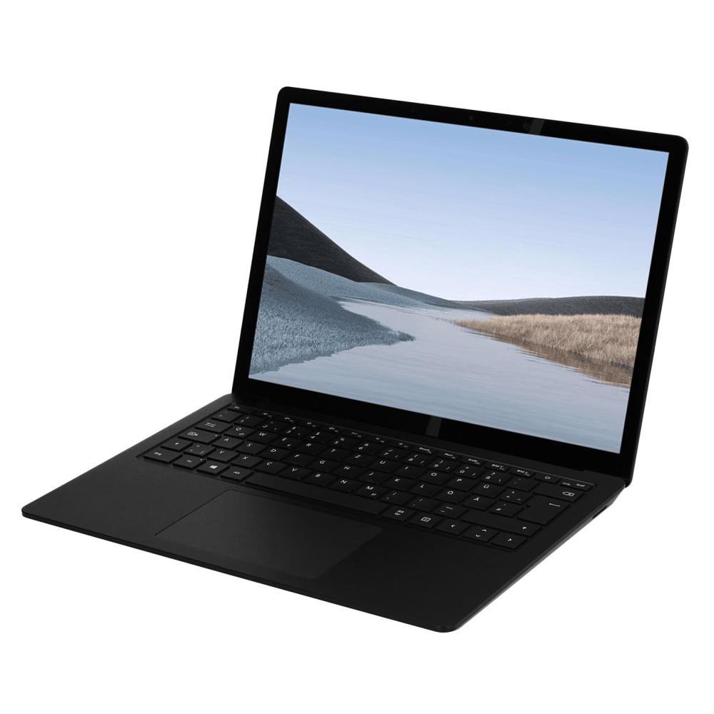
I bought a Surface Laptop 3 (AMD) in 2020 as it seemed to be a really well built Laptop that could rival the construction of a MacBook. I did not want to buy a Mac this time around as it was not clear if you would be able to run Linux on the Apple Silicon Macs ever.
In hindsight it turns out you can with Asahi Linux ...
The odysee began. First the Audio controller had a hardware bug that lead to Bluescreens on each and every standby/hibernate cycle. I sent the Laptop back and got a new one.
That one had severe latency problems, when you're using Wifi the audio would stutter badly. Sent that one back too. The new one had exactly the same problem. Usually I would have gotten a lawyer and told them to get me my money back at this point, but this was the year of the big C, so no dice. I switched to a Lenovo Yoga 7 slim and the Surface Laptop was used by my girlfriend on Linux where the audio stuttering was no problem.
Later on she got the Macbook I should have bought in the first place...
Linux on that laptop is quite a good experience but you won't be able to use the touchscreen.
Recently I felt the need to be able to run Windows on a machine again for CAD reasons. Now the audio stuttering annoyed me so much I went for drastic measures.
The solution
So what's causing the audio stuttering on Windows that does not affect Linux on this Laptop? Simple answer: Bad drivers... for Windows... on a Microsoft built laptop...
Thanks man.
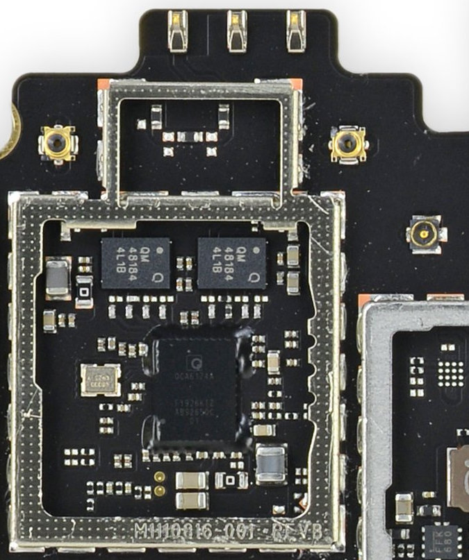
You cannot replace the Wifi module as they decided to integrate that with the Mainboard.
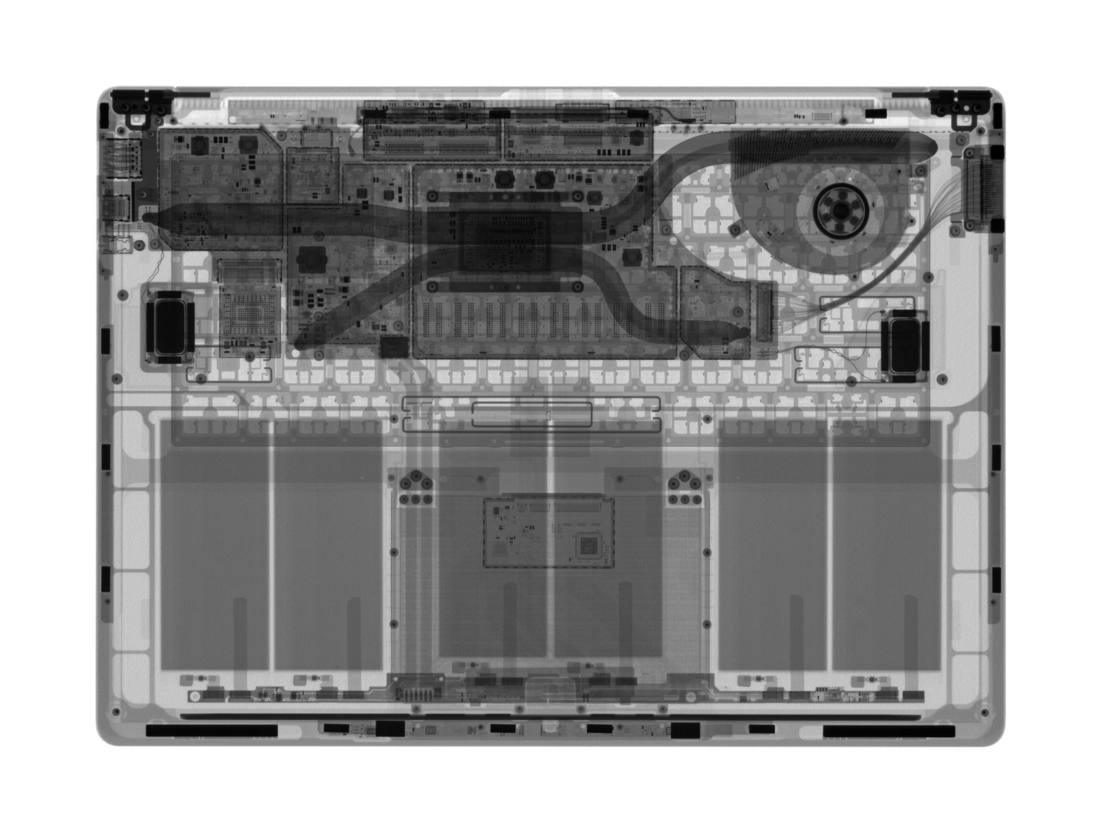
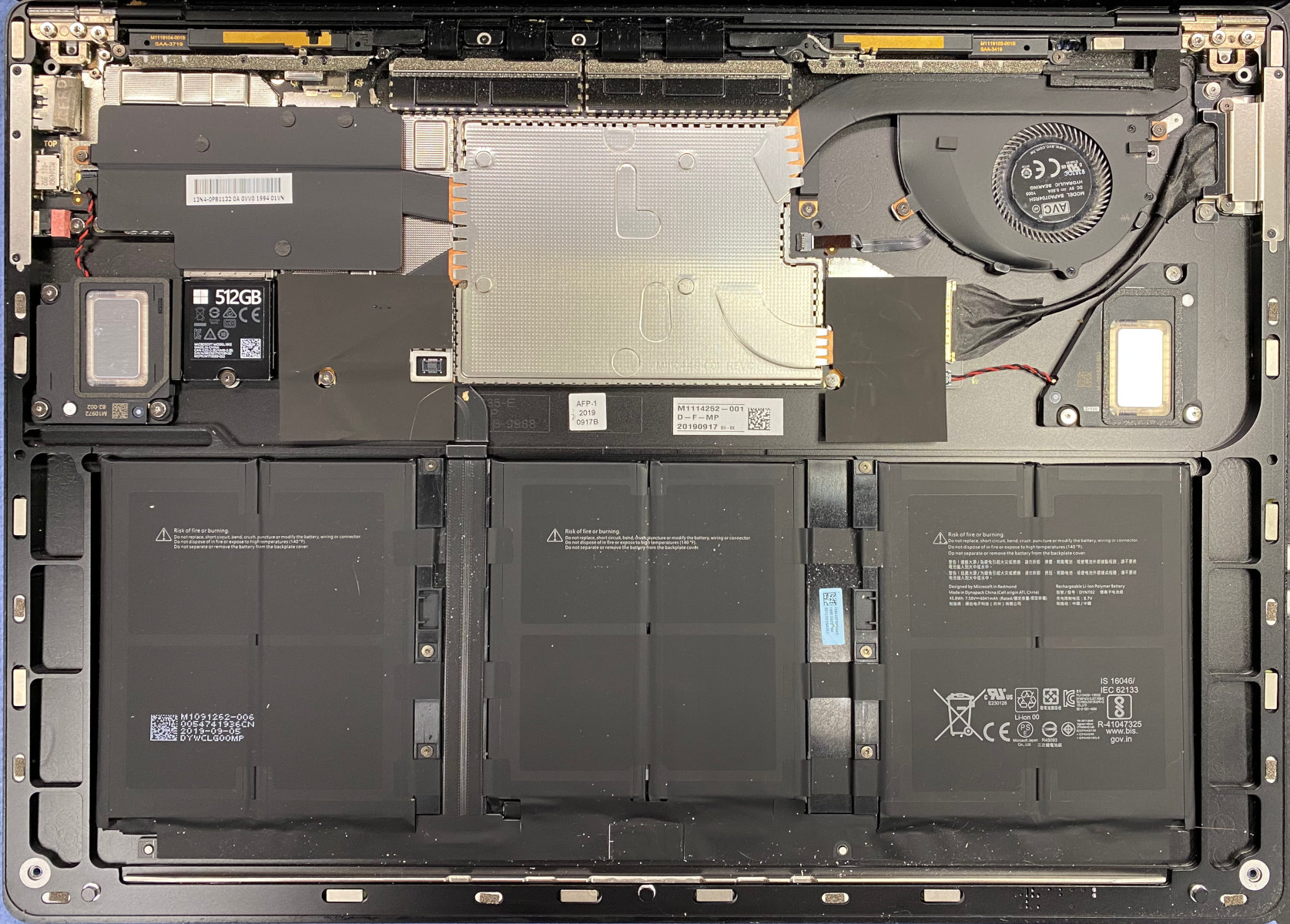
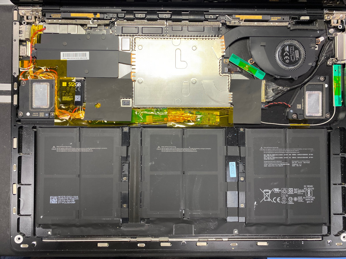
This laptop can be opened by removing 4 screws and the rest is magnetically attached, quite nifty, but I have to ask Microsoft: Why? The only thing you can replace is the SSD (I mean that's better than Apple but still). The Battery is glued in without any rubberband release strips like Apple does it, the Mainboard contains the soldered RAM... You can exchange the dock port and the audio jack, but the USB ports are soldered to the mainboard again, but back to the topic:
The solution here is to disable the Qualcomm Wifi and Bluetooth stuff in device manager and use USB sticks to replace the functionality. As I don't want a USB hub dangling from the laptop all the time I investigated if there is space in the case to drop additional hardware in. Turns out: There is! They did use the mainboard of the 13 inch laptop on the 15 inch, as well as the same battery on both versions so you have quite a lot of space.
Reverse engineering the Surface dock connector
What is the Surface Dock connector you ask? Simple, Microsoft
stole
licensed Apples
Magsafe "attached connector via magnets" thing and created a reversible (caveat emptor)
connector that can charge the laptop as well as be a docking port to an external dock
that you can leave on your desk for a simple one cable docking action.
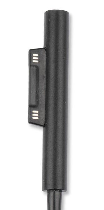
You can find people on the internet who have reverse engineered the pinout of the Dock connector. Turns out it carries USB2, USB3 and Display Port lanes in addition to the charge input. So my idea was to steal the USB lanes from that port as I own no Surface Dock anyways and the connector was used for charging only.
There are some problems with that:
- The connector does not carry 5V output only 12V input as it is thought to be used for a dock only.
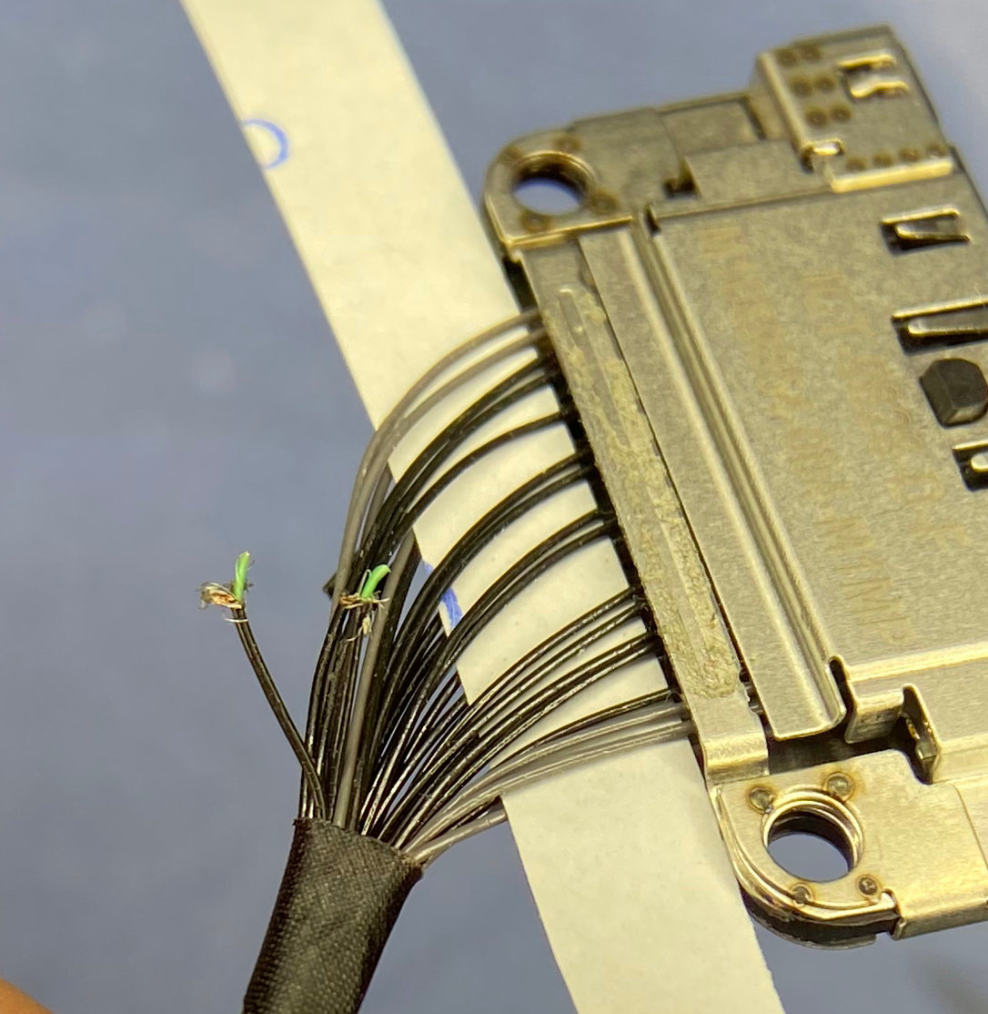
- The connector pinout is known but it is asymmetrical with an exception of the power input pins. So it's a bit complicated to determine which pins are what.
- As it turns out later on in my exploration: The cabling from the mainboard to the connector uses micro coax cables which are impossible to solder to as they are absolutely tiny.
Changing gears, let's steal the USB-A port
As I ran into a dead end (ok, a 17 Euro replacement part dead end) with that dock connector but was determined to make it happen. What am I connecting to the USB-A port on that laptop anyways? A logitech wireless dongle? An USB stick? Ok sometimes but we have a USB-C port in addition to the A one.
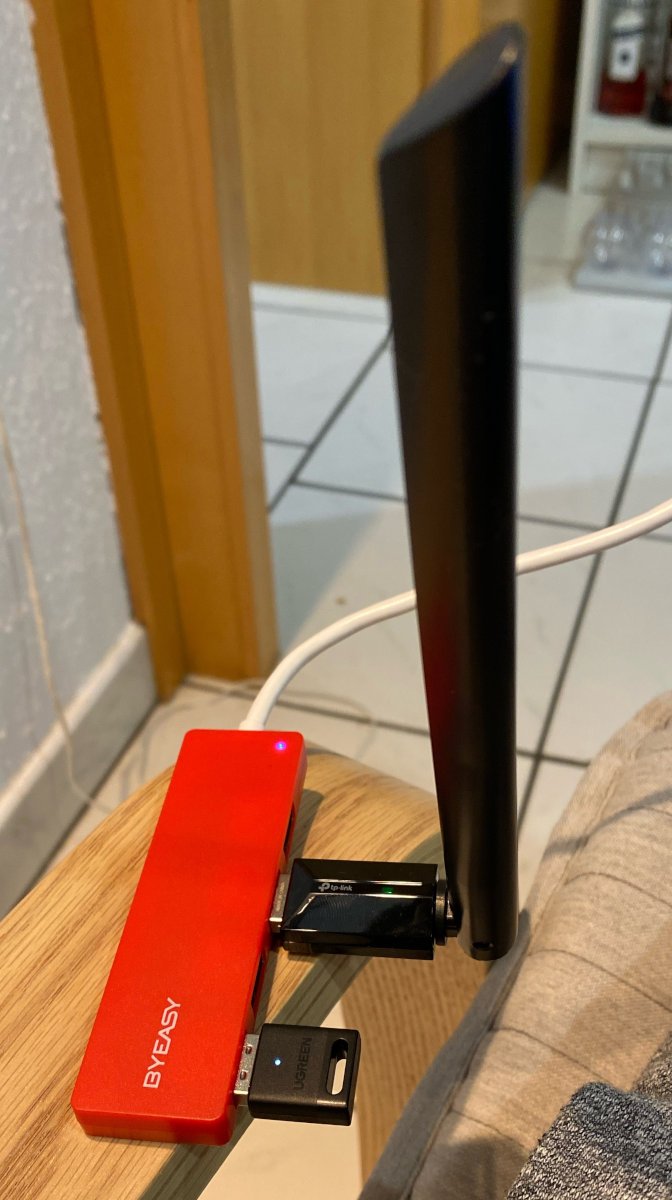
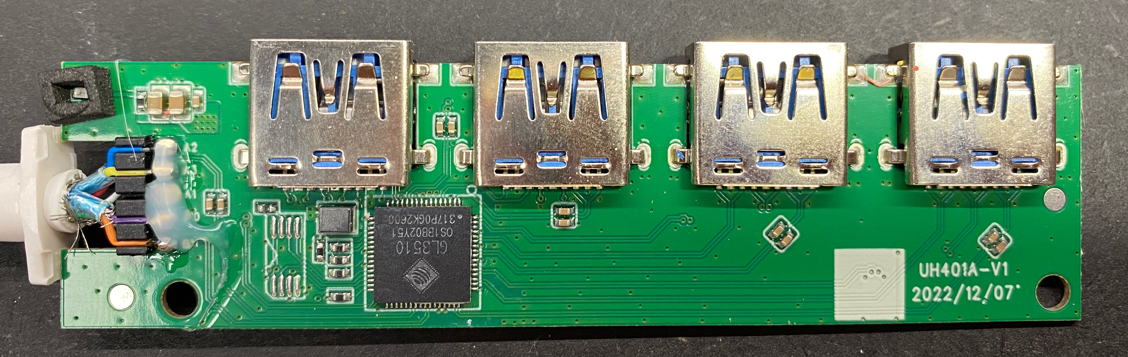
The USB hub has 4 ports... so if I use one port for Wifi, another one for Bluetooth I have 2 available. I could add that Logitech dongle, as they are really small, directly into the laptop and still have one port free.
So how do I get to the USB port contacts? Well...
Dismantling the complete laptop
As I wrote above, I am not sure why Microsoft did go all the way to magnetically close the laptop. This manifests now in even deeper facepalms.
To get to the screws that hold the mainboard in you have to remove a lot of clip-on shielding cans (at least they are clipped on not glued). In the process of this mod I removed the mainboard 3 times, so forgive me as the shields lost a few clips in that process. That construction is just infuriating as the complete laptop is made of aluminium so you could probably use that as shielding if done correctly and just not bother with all the clip-ons.
To be able to route the cables underneath the mainboard I had to modify the case a bit, some aluminium bridges hat to be filed down a bit to fit the cables in.
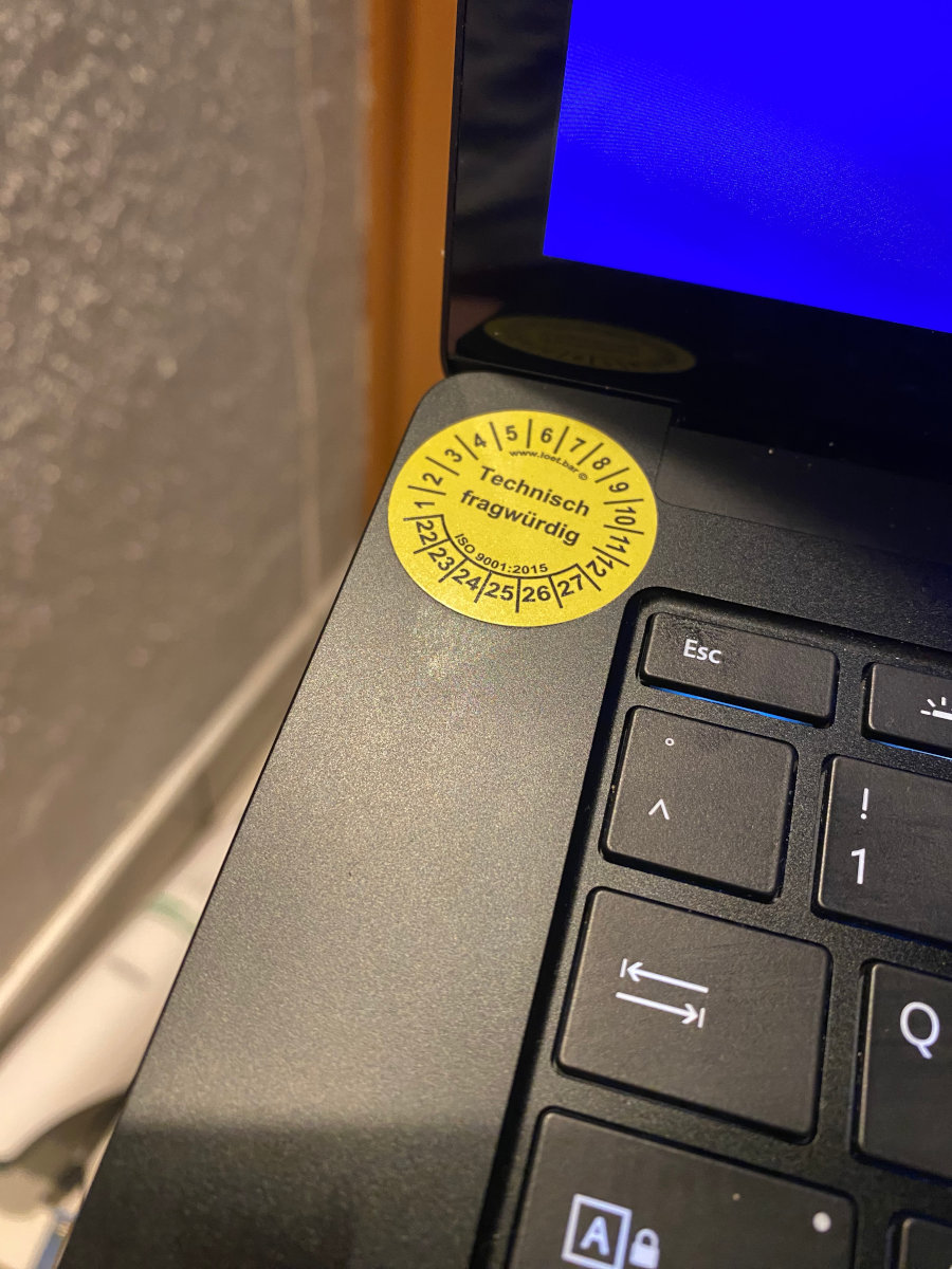
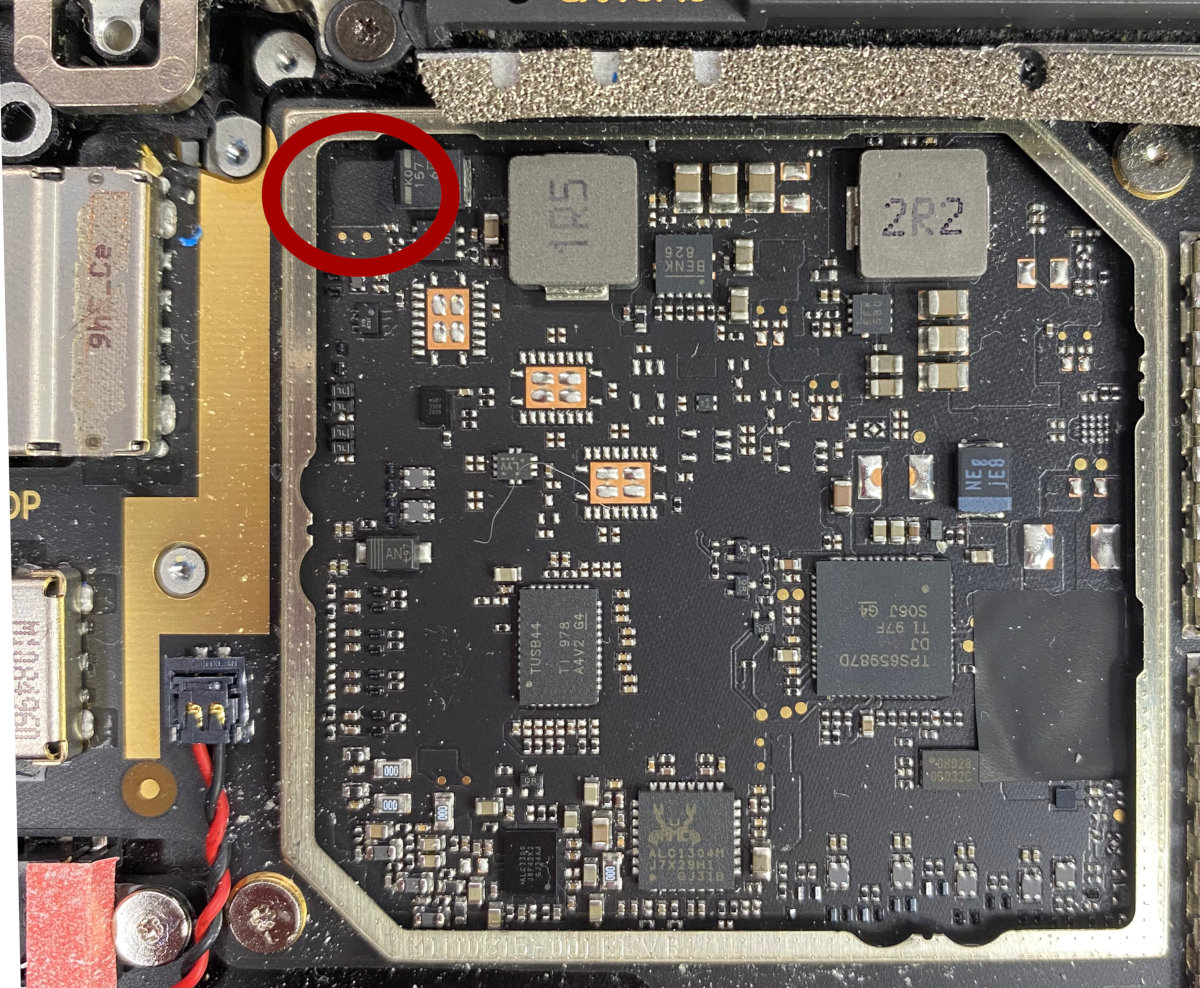
I could not fit power cables underneath the mainboard so I had to hunt down a source of 5V power from somewhere, turns out the leftmost shield can houses the USB PD controller as well as battery charging circuit and for unknown reasons to me the audio circuit. Why would you include the audio stuff in the same shielding can as the high-power stuff? I don't understand, I would have put them in two seperate compartments... Yeah well the "technically questionable" sticker on the laptop makes more and more sense now.
USB 3 is... something
So the wifi USB stick is a USB 3.0 stick because it can do 1.3 GBit/s theoretically. It works on USB 2 but then it's just a bit slower. Additionally USB 3 does use less CPU power than 2 (it seems strange but makes sense) and should be the better protocol in almost all cases.
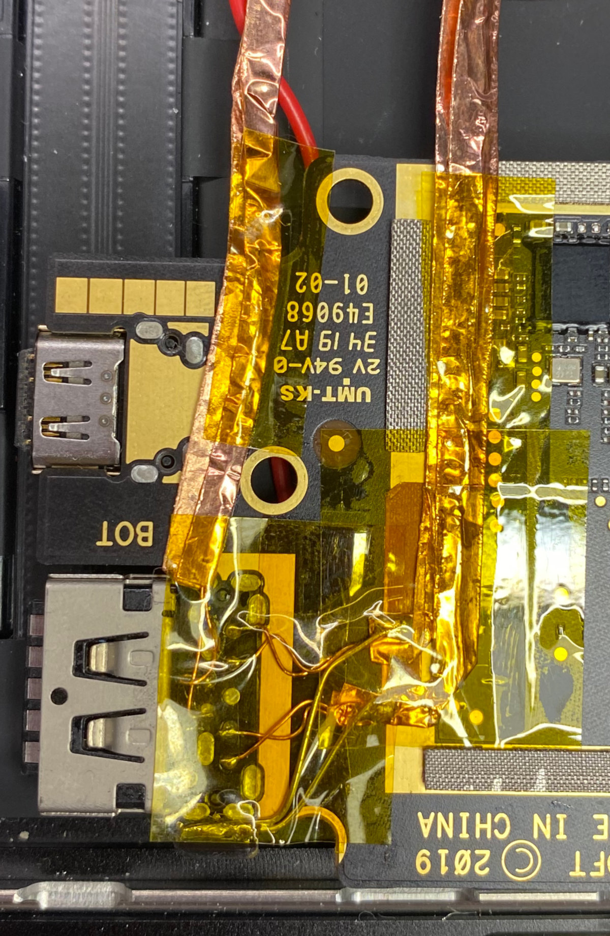
There's one problem though: It's fricking fast with 5 GBit/s minimum speed, so cabling has a bit more requirements than USB 2. And this is why I had to rip out the mainboard three times. The first attempt did not use much shielding, the device wasn't even detected as "unknown". The second attempt proved very unstable and the third attempt I was in "yolo"-mode and put everything under a layer of copper tape... Turns out this was exactly what was needed.
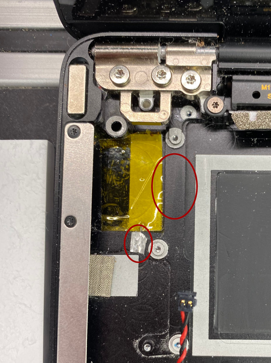
This here was not enough shielding:
A small detour
How does USB even work? The "ancient" specification of the original USB did provide two speeds: Low speed (1.5 Mbit) and Full speed (12 Mbit). At those speeds you can forgo most shielding and probably run the signal over wet noodles (now I have to try that).
As the standard is from 1996 you could understand why that is. At that time 12 Mbit was
pretty fast. They did improve over RS232 serial connections by using a pair of twisted
wires for differential signaling (
D-
and
D+
), the idea is that one wire has the
signal in original form (
D+
) and the other one has the exact inverted signal. If you
introduce an external interference this will affect both wires at the same time and you
can read the signal by comparing both lines. For example if you get a disturbance that
induces, let's say 3 Volts into both wires, one will have 6.6 Volts and the other one
3 Volts. The difference between both lines will be still 3.6 Volts and you can still
read your data.
In USB 1 and 2 you'll be using 4 lines, Power, the differential data pair and Ground.
You have to make sure to connect
D+
to
D+
on both sides of the cable. USB 1 and 2
differential pairs do not use negative voltages, just zero and "something". USB 1 uses
3.6 Volts, USB 2 much lower 0.45 Volts. The wires are twisted so they will not emit much
EMI and when a disturbance hits them it will hit both wires to the same degree. Cables
are usually shielded with one shield around the complete cable.
USB 3 is another beast. It uses two differential pairs
RX
and
TX
and as you can see
from the names alone, it does not share one pair for both directions of communication.
It also uses another form of encoding that works much more like PCI express than the
older encoding. This is done because the encoding alone will suppress some of the EMI
of the cable because of it's balancing, but this will go to far for this post.
The interesting thing about USB 3 here is: The cables are cross over cables, so the
RX
line will go to the
TX
terminals and vice versa, but as the link training that
is needed for the receivers on the high speed line interface can detect the polarity
of the
+
and
-
lines you can connect the differential pair in either direction.
Very nice... would be cool if I knew that before doing this project...
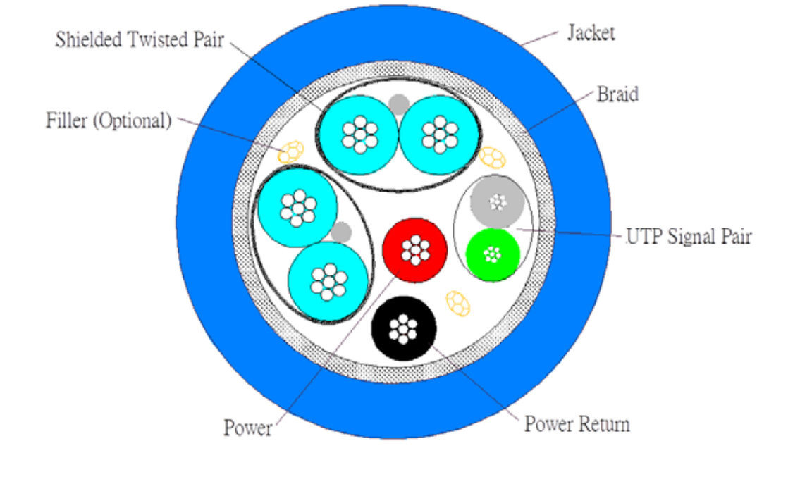
As we're still talking about a digital interface and we're trying to transmit and receive 5 Gbit/s the requirements for shielding go through the roof. Both differential pairs have to be twisted and shielded from each other as well as the world. As we need a very stable ground path at those speeds there is a drain wire embedded with the twisted pair that acts as a signal ground return. It is not clear to me from the specs if that wire may or may not be connected to the same ground as the shielding. But as I looked into the USB hub... they did just that.
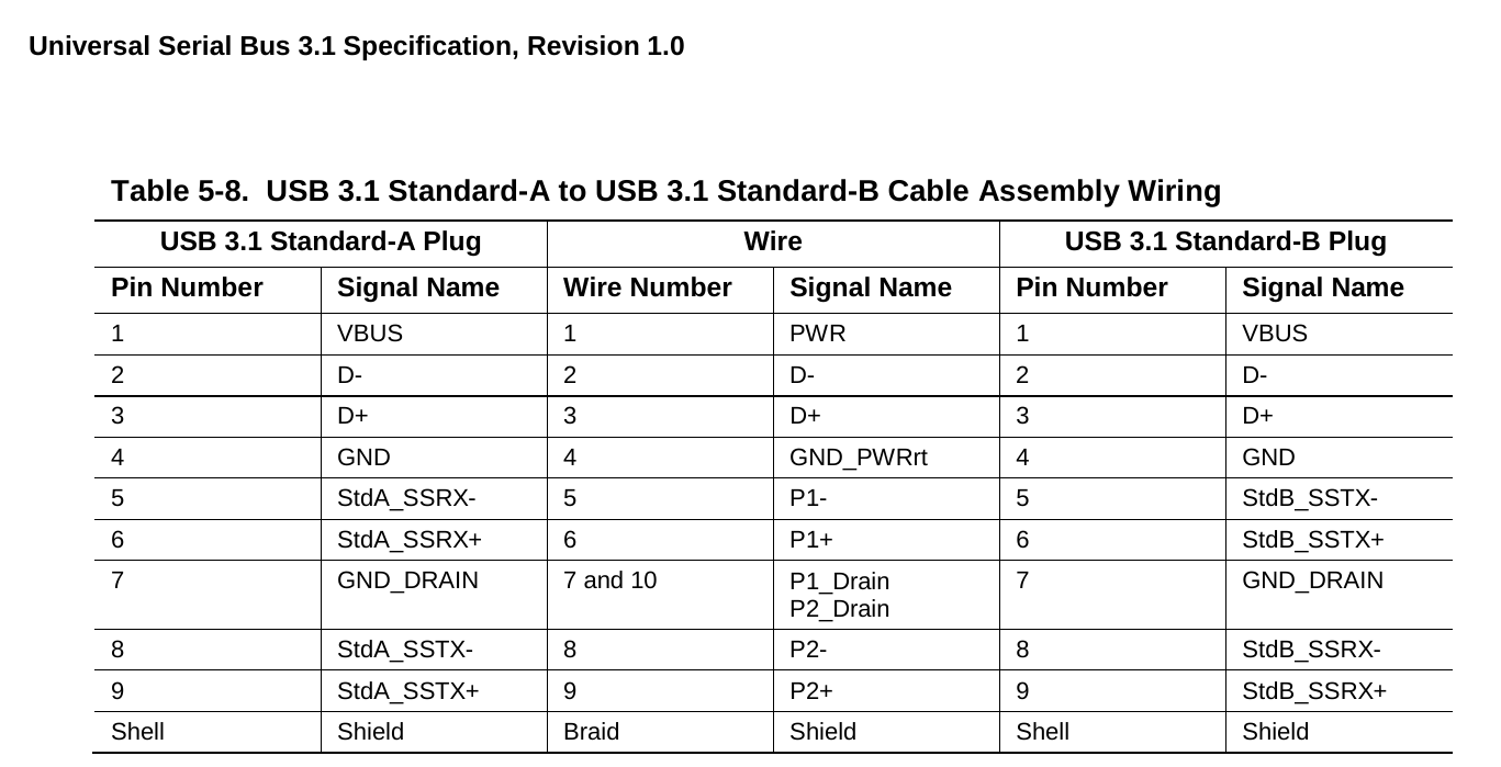
Oh by the way: USB 2 and USB 3 do not share any data lines, a USB 3 port is basically
a USB 2 port and a USB 3 port in one connector, the old
D+
and
D-
are completely
seperate and even use different host controllers, so if you have two devices, one USB 3
and one USB 1/2 you could basically split a port without even using a hub.
Back on topic
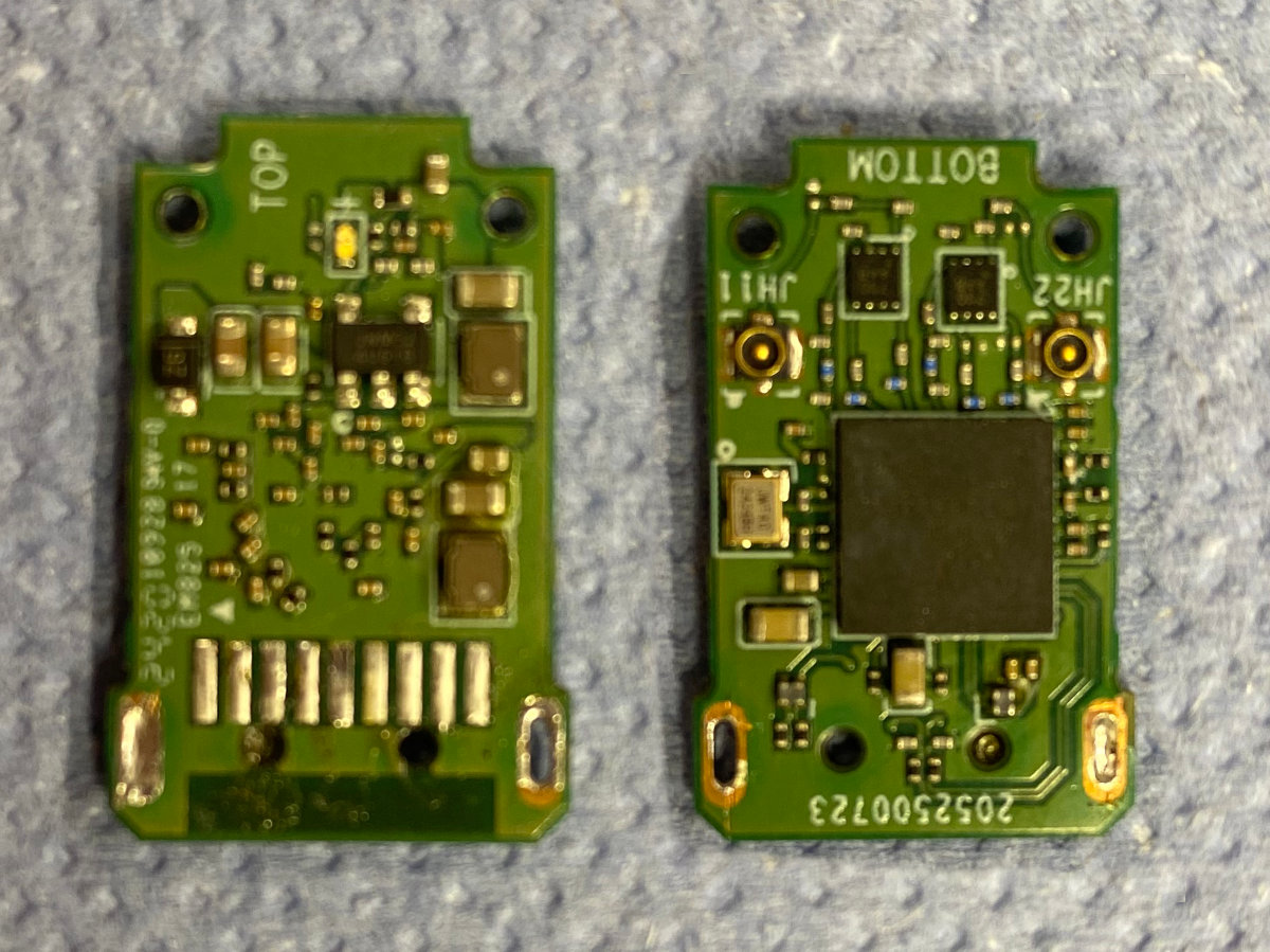
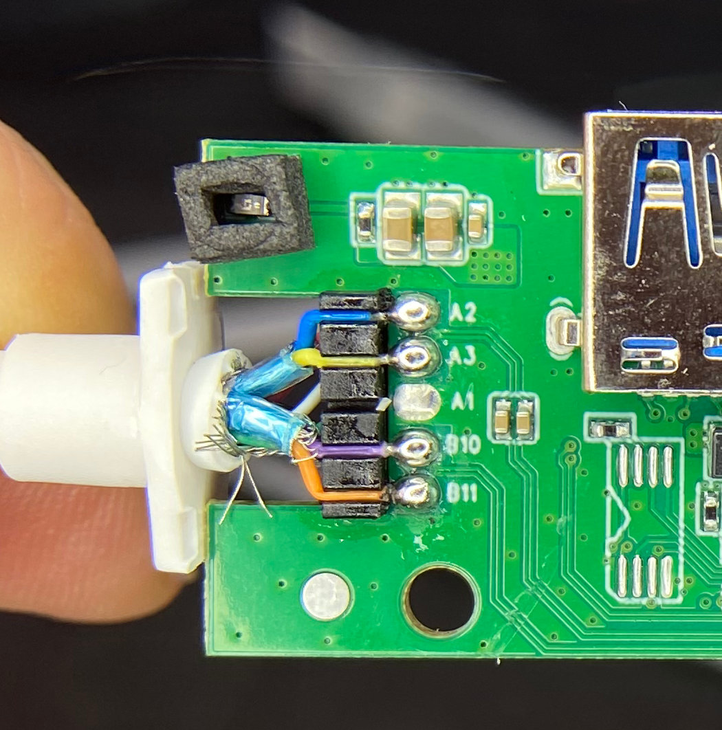
You can see I stole the data lines from the USB-A port, re-inserted the mainboard and connected that to the PCB of the USB hub.
If you're wondering: Yes I absolutely took a Dremel to the PCB of the hub and antenna of the wifi stick and cut stuff off. There was nothing on there, it was just "structural".
After hardwiring everything in with enamel wire (also known as transformator wire. It's basically copper wire with some kind of coating on there to avoid short circuits) and using copious amounts of copper tape to shield everything with a lot of swearing and probably rebooting the laptop about 100 times it finally worked.
After that it was just a lot of puzzling to get everything in there.
Finishing words
It's interesting on what you can do that should be impossible if you ask someone who designs PCBs for a living. Probably I am just lucky that it works, probably the hardware can take more "abuse" than most people think, but probably it's just good enough. It would be interesting to actually measure the insertion losses and impedances of those hacked wires but I don't have the equipment, nor the knowledge to do that.
So does it work then? Yes, yes it absolutely does. I am even a bit impressed how good the Wifi signal is in that aluminium box of the laptop. It seems the keyboard is "leaky" enough to let the wifi signal through.